Comb filters get their name from the shape of their magnitude response and are important components of audio signal processing networks.
- A feedforward comb filter is illustrated in Fig. 20.
Figure 20:
A feedforward comb filter block diagram.
![\begin{figure}\begin{center}
\begin{picture}(3.9,0.8)
\put(0.27,0){\epsfig{fil...
...0.67){$b_{0}$}
\put (3.9,0.12){$y[n]$}
\end{picture} \end{center}
\end{figure}](img124.png) |
- The difference equation for this filter is given by:
- The transfer function of the feedforward comb filter is
from which the amplitude response is found as
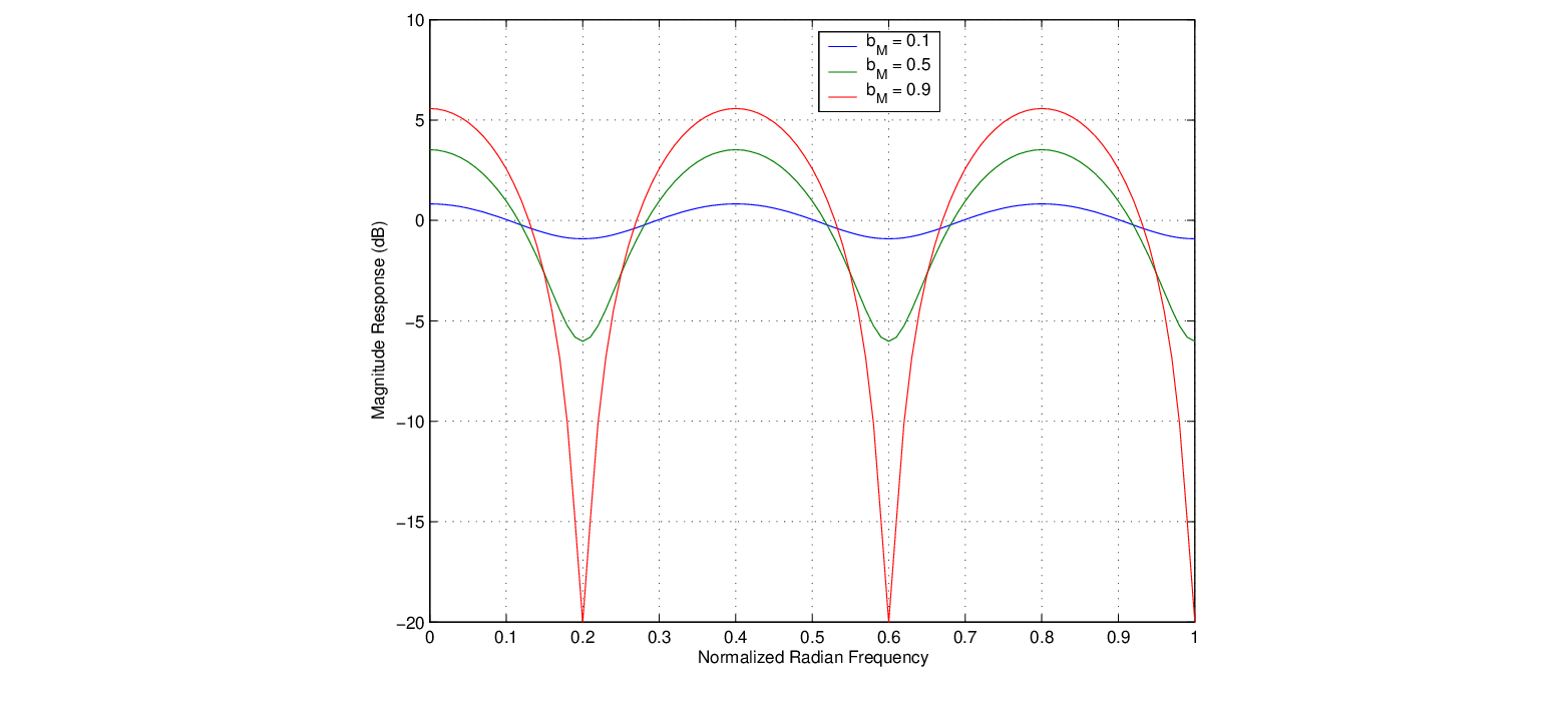
- The magnitude response of a feedforward comb filter, calculated with the Matlab script combs.m, is shown in Fig. 21 for
 ,
,  , and
, and  = 0.1, 0.5, and 0.9.
Figure 21:
Magnitude response of a feedforward comb filter with , , and = 0.1, 0.5, and 0.9.
 |
- The portion of the signal processing block diagram within the dashed lines at the bottom of Fig. 19 is a feedforward comb filter.
- Depending on the distance between the direct and reflected paths, certain frequency components in the sound will be destructively cancelled at the listener position, corresponding to the notches in the frequency response of the feedforward comb filter. In this way, the feedforward comb filter is a computational physical model of a source-listener arrangement involving a direct and single reflected path.

| ©2004-2022 McGill University. All Rights Reserved.
Maintained by Gary P. Scavone.
|
![$\displaystyle y[n] = b_{0}x[n] + b_{M}x[n-M].
$](img125.png)