Next: Diameter and Taper Discontinuities Up: Conical Air Column Modeling Previous: Reflection at a Rigid Boundary
 for this system can be determined by calculating its response to a unit volume velocity impulse and transforming it to the frequency domain using the DFT.
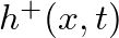
![$\displaystyle h^{+}(x,t) = \frac{\rho c}{A(x)}\left[ \delta(t) - \frac{c}{x} \,e^{-(c/x)t}\epsilon(t)\right],
$](img137.png) (26)
(26)
 is the Heaviside unit step function.
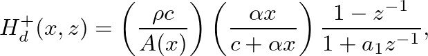
 in the discrete-time domain.
 (27)
(27)
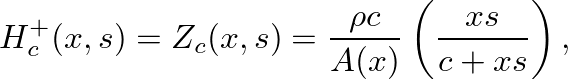
 is the spherical-wave surface area at
 (28)
(28)
 is the bilinear transform constant and
  is equal to the allpass truncation filter coefficient given in Eq. (25).
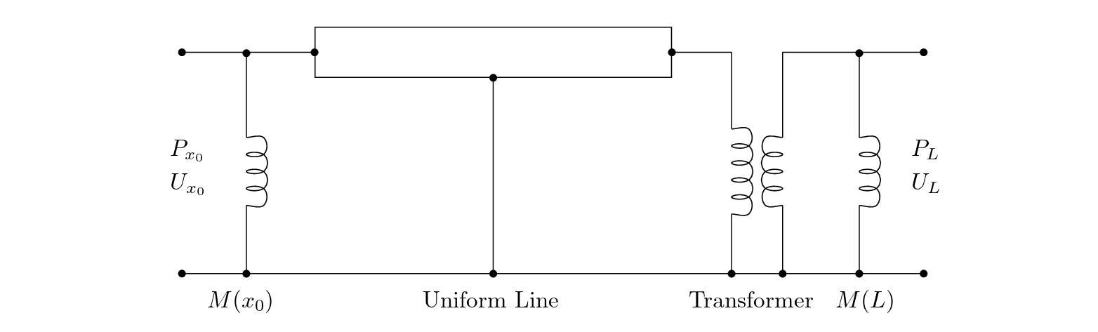
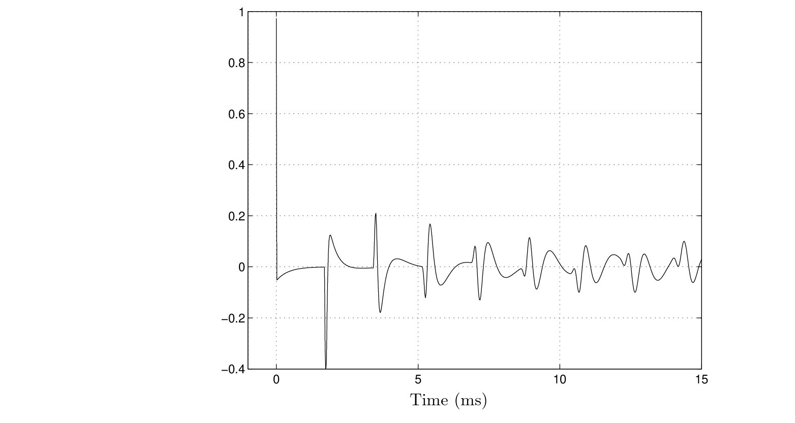
 of a closed-open truncated cone is found from the digital waveguide structure of Fig. 7 as the pressure response at
  to the impulse response
 output scale factors are appropriately weighted by
 calculated using a Levine and Schwinger model of the open-end radiation and neglecting viscothermal losses.
 |

| ©2004-2022 McGill University. All Rights Reserved. Maintained by Gary P. Scavone. |