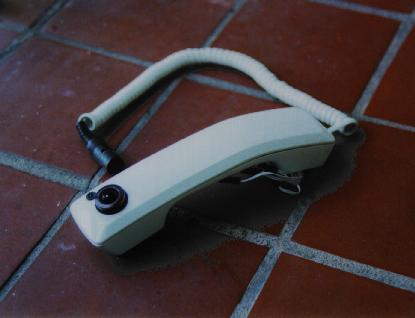
Figure 1. The Phoney Controller from above.
The Phoney Controller consists of a telephone housing, four Force Sensing Resistors (FSRs), an Analog Devices ADXL202 two-dimensional accelerometer, a BASIC Stamp II (BSII) microcontroller, a stupid "on-off" switch, and a cool LED! I am essentially using the BSII as a MIDI sequencer. All sounds at this point have to be generated from an external MIDI synthesizer. The FSRs and the 2D accelerometer are used to control various aspects of the sequencer. This work is a variation on a theme started by Perry Cook at Princeton.
What is it for?
In part, the Phoney Controller was built to serve as a "one-man band" at my wedding. But mostly, it was build for goofing around and having fun. Given the memory limitations of the BSII, sequences have to be pretty short. That's the challenge ... coming up with simple but interesting patches that someone will enjoy improvising with for hours.
What does it look like?
Look no further! Here's a shot from above and one from below. The FSRs are currently taped to the underside of the handle
Figure 1. The Phoney Controller from above.
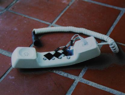
Figure 2. Another view of the Phoney Controller.
What's inside?
Here's a couple shots of the guts. The battery and telephone jack pretty much take up all the space where the microphone used to go. I managed to cram the circuit board into the other end. You can see the 2D accelerometer mounted on the board itself, along with the BSII and other assorted resistors and capacitors.
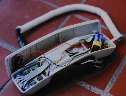
Figure 3. The guts of the Phoney Controller.
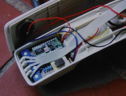
Figure 4. A closeup of the circuit board of the Phoney Controller.