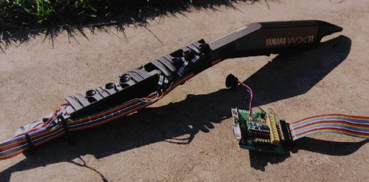
Figure 1. The Holey Controller with BASIC Stamp II microcontroller.
The Holey Controller is a modified Yamaha WX11 MIDI wind controller that I created for use in playing my digital waveguide woodwind instruments (see my thesis for more information). Using digital waveguide techniques, I developed an efficient model of a woodwind tonehole that accurately simulates all the states of the hole from fully open to closed (see Real-time Computer Modeling of Woodwind Instruments [with Perry R. Cook] in my online papers page). I then implemented an eight-hole woodwind model using the Synthesis ToolKit in C++ (STK), which allowed me to manipulate the various toneholes in realtime. The problem then became, "How do I control this model?" All currently available MIDI wind controllers output a single MIDI note number for any particular fingering ... no matter how unconventional this fingering may be. Further, these instruments provide no intermediate finger position information for finger states BETWEEN open and closed.
THE SOLUTION
So, the idea was to take the Yamaha MIDI wind controller and place Force Sensing Resistors (FSRs) under each key to determine the key positions. Between the FSRs and the key, a small piece of foam was inserted. In this way, the FSR was driven in its initial highly nonlinear range. Each FSR was connected via ribbon cable to a BASIC Stamp II microcontroller, which was used to determine the key position and output the result in the form of MIDI ControlChange messages. Because I am also using breath pressure MIDI messages from the WX11, I merge the two MIDI channels before inputing the result to my STK instrument. Figure 1. shows the complete MIDI wind controller system with BASIC Stamp II microprocessor. Since taking these pictures, I finally put all the electronics into a nice "belt-clip" box.
Figure 1. The Holey Controller with BASIC Stamp II microcontroller.
Figure 2. shows a closeup of the FSR/key setup. The FSRs were taped to the WX11 and attached to the ribbon cable with two-pin socket connectors.
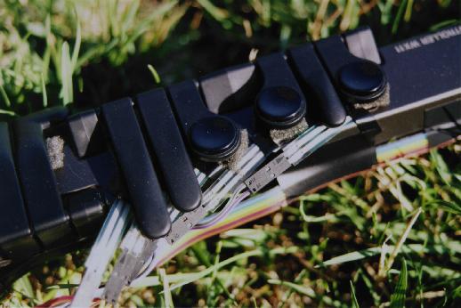
Figure 2. Closeup of the FSR/key setup.
MORE DETAILS
The BASIC Stamp measures the FSR resistance value via an RC circuit setup. By setting a BSII pin high for one cycle count, the capacitor is charged. The microcontroller then measures the time required for the capacitor to discharge to a "pin low" value. Because of the number (10) of RC circuits used with the Holey Controller, I used small capacitors to keep the RC-times relatively low. I also used trim pots in parallel with the FSRs to calibrate each circuit.