1x
8x
4x
2x
∞
∞
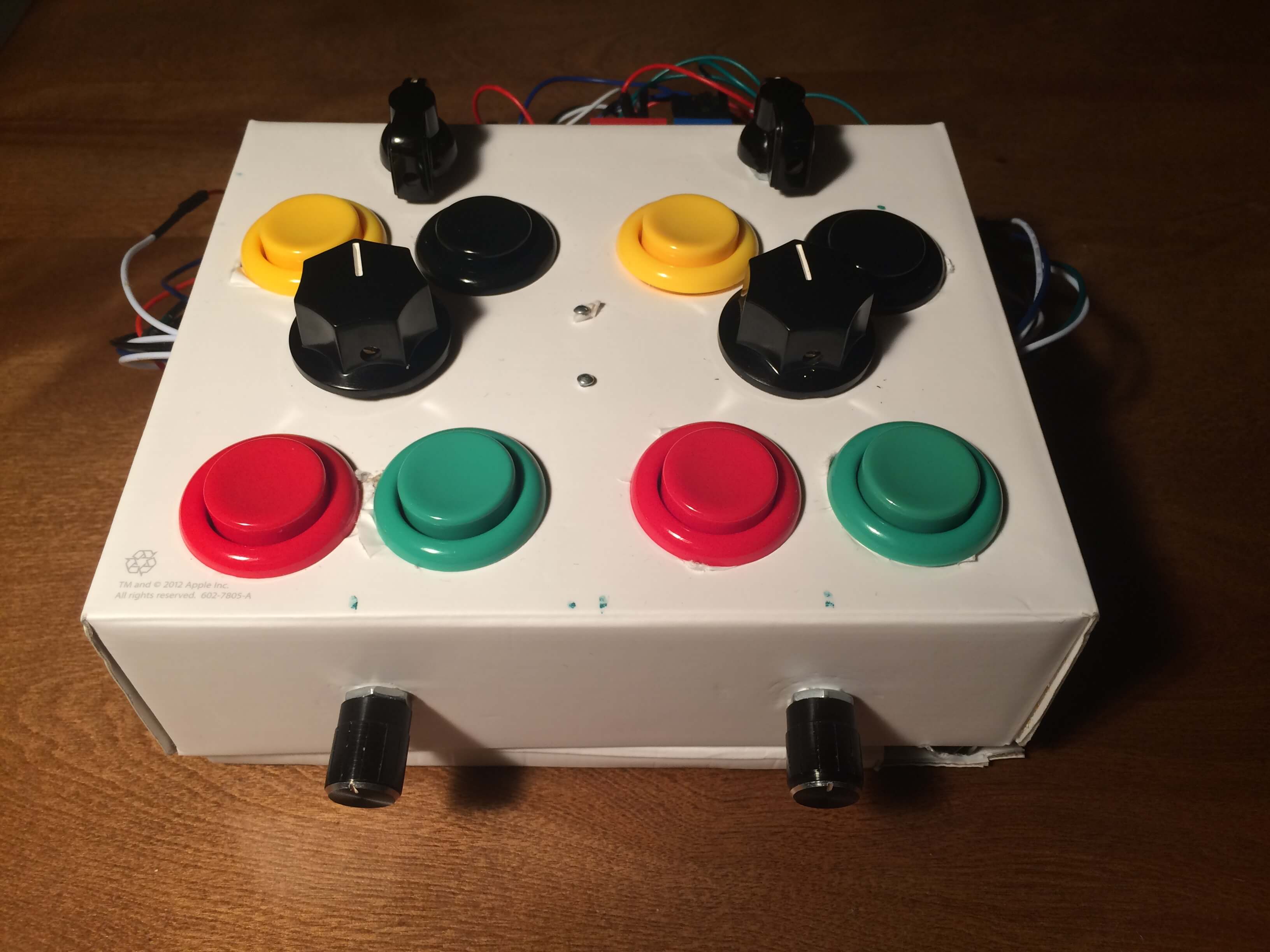
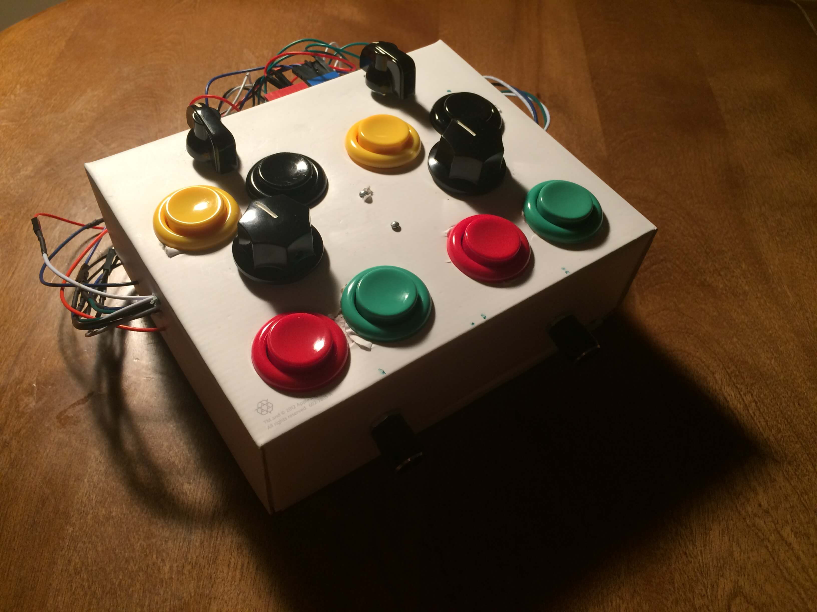
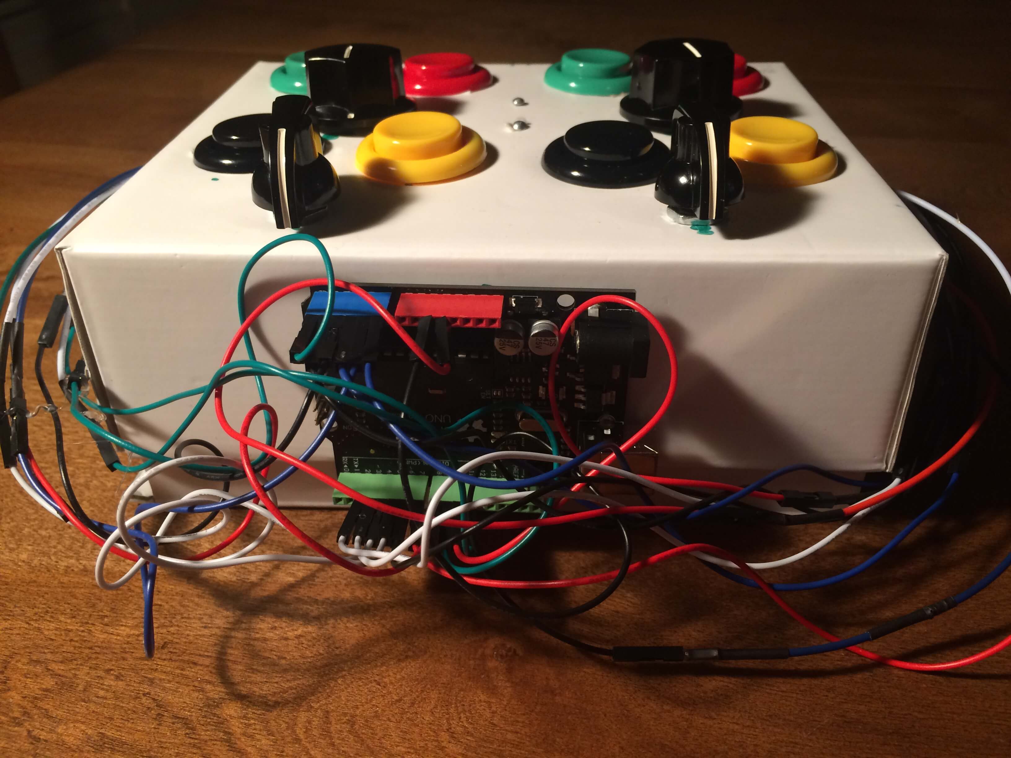
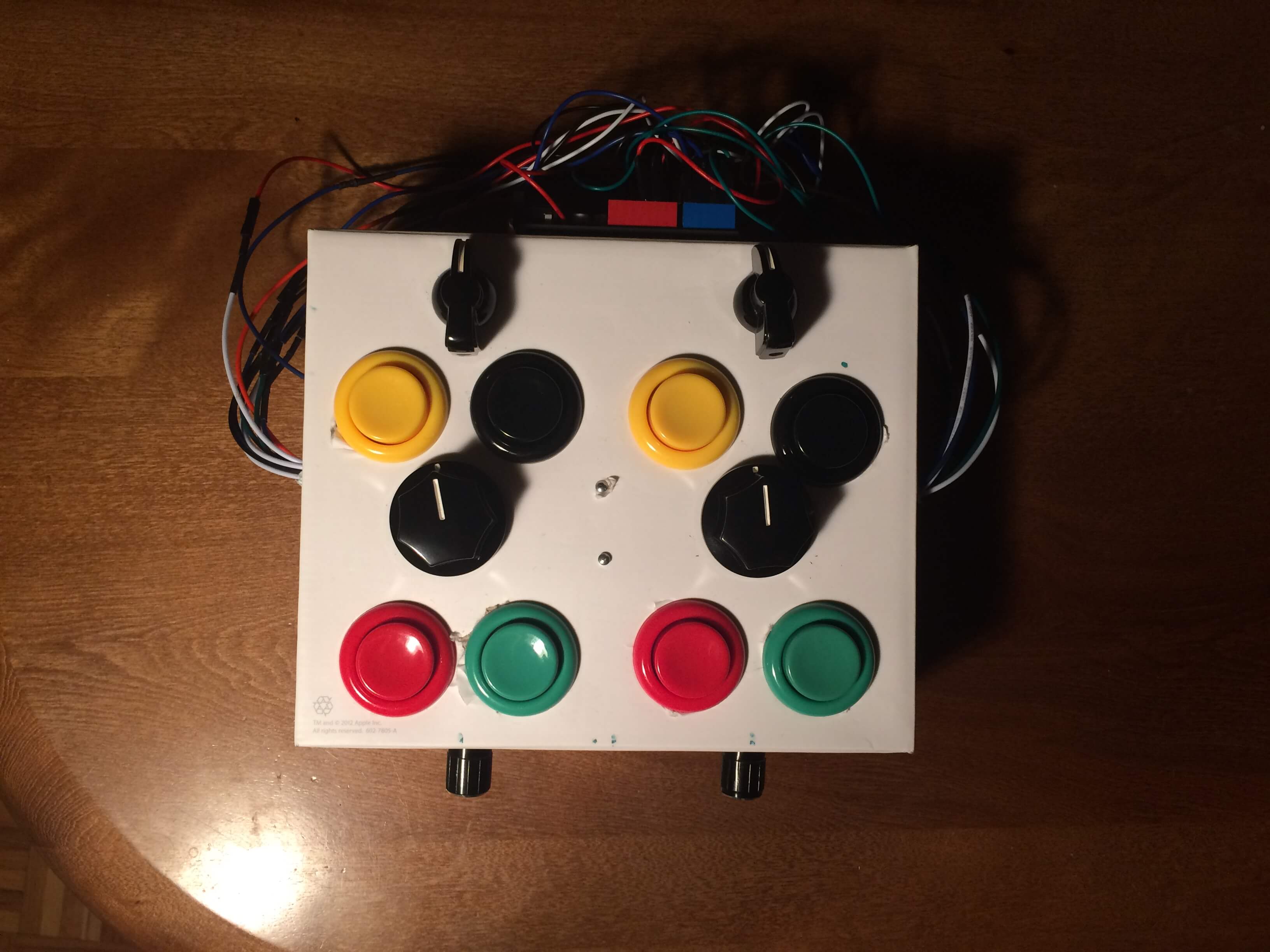
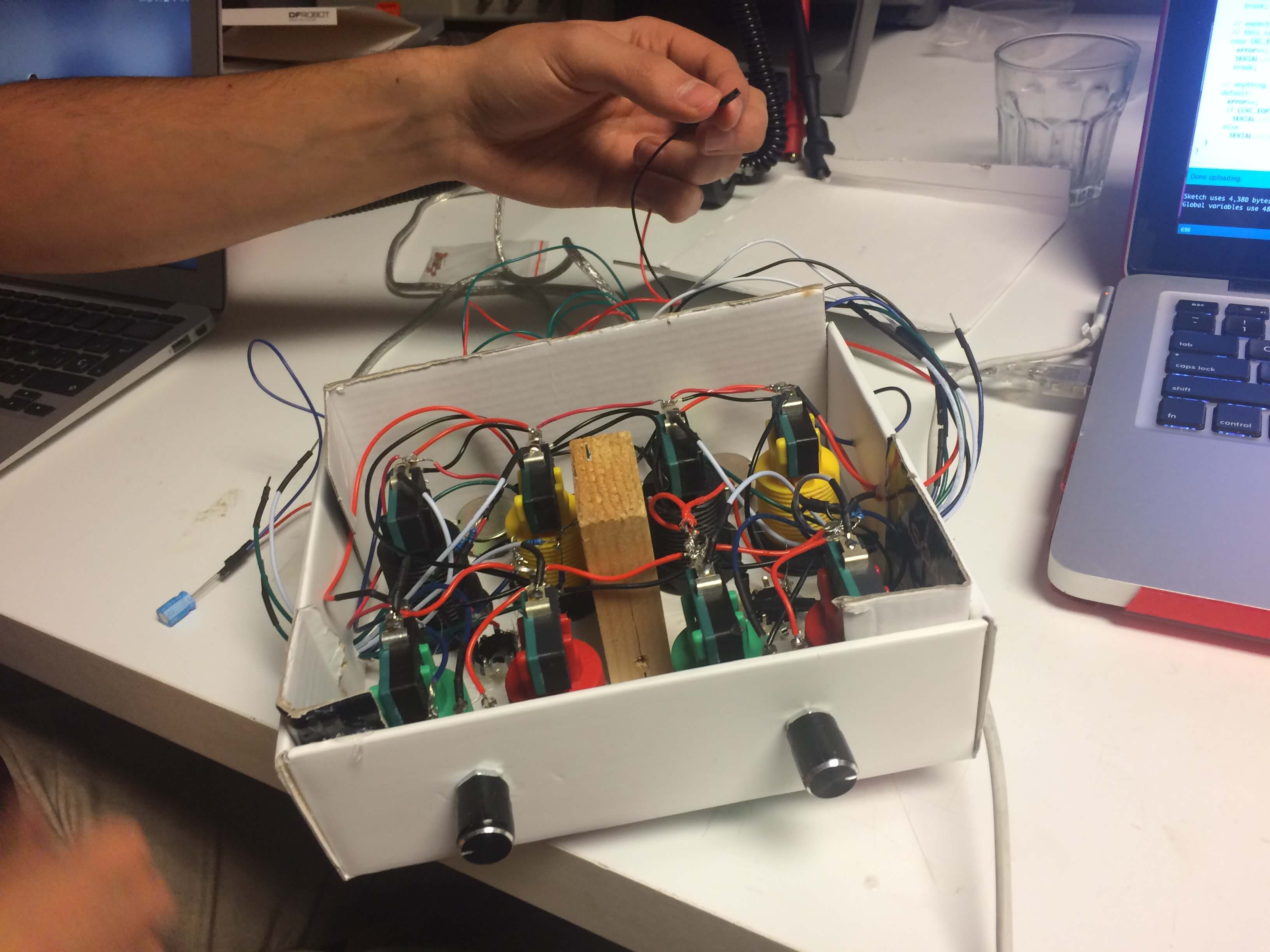
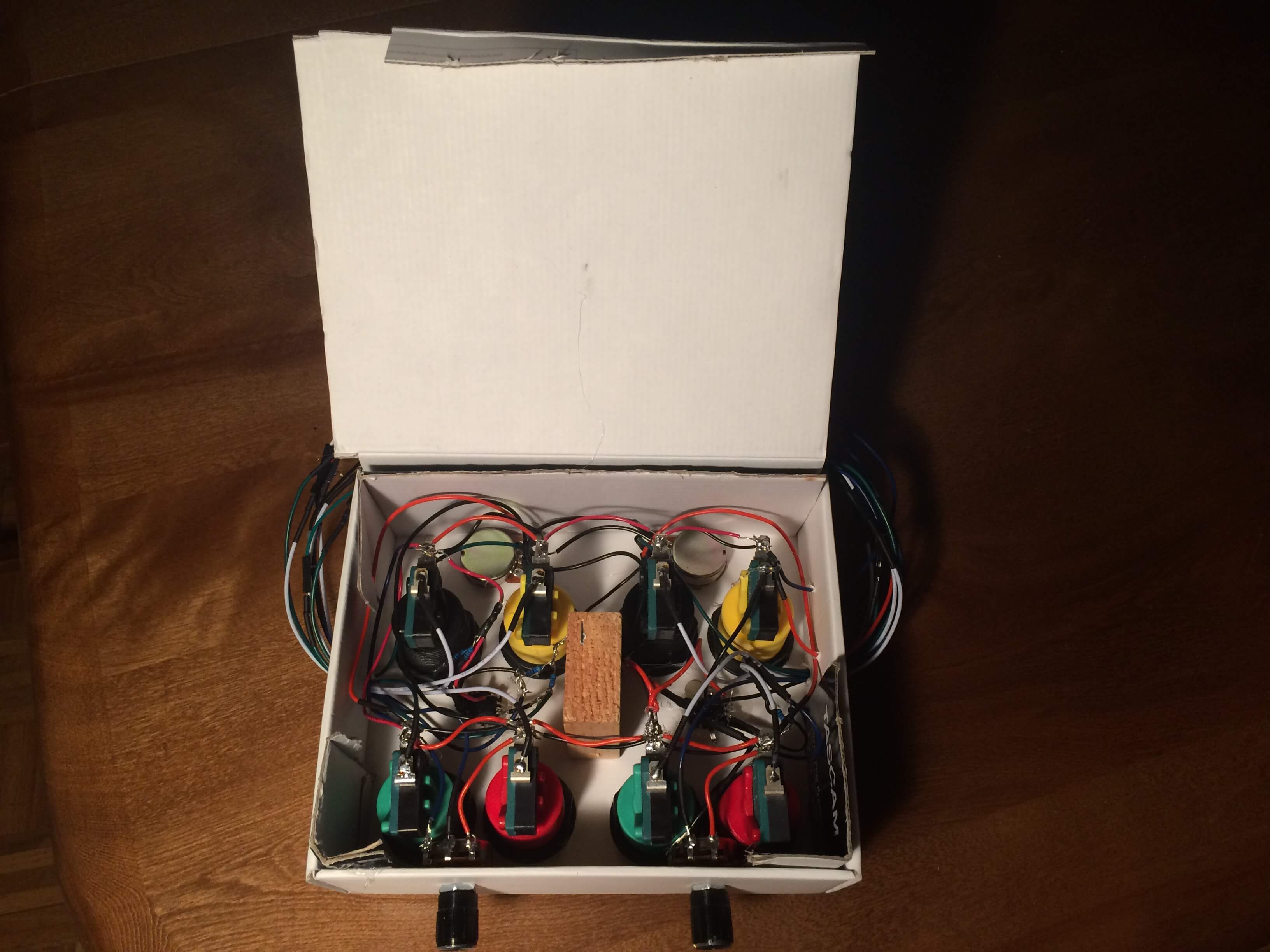
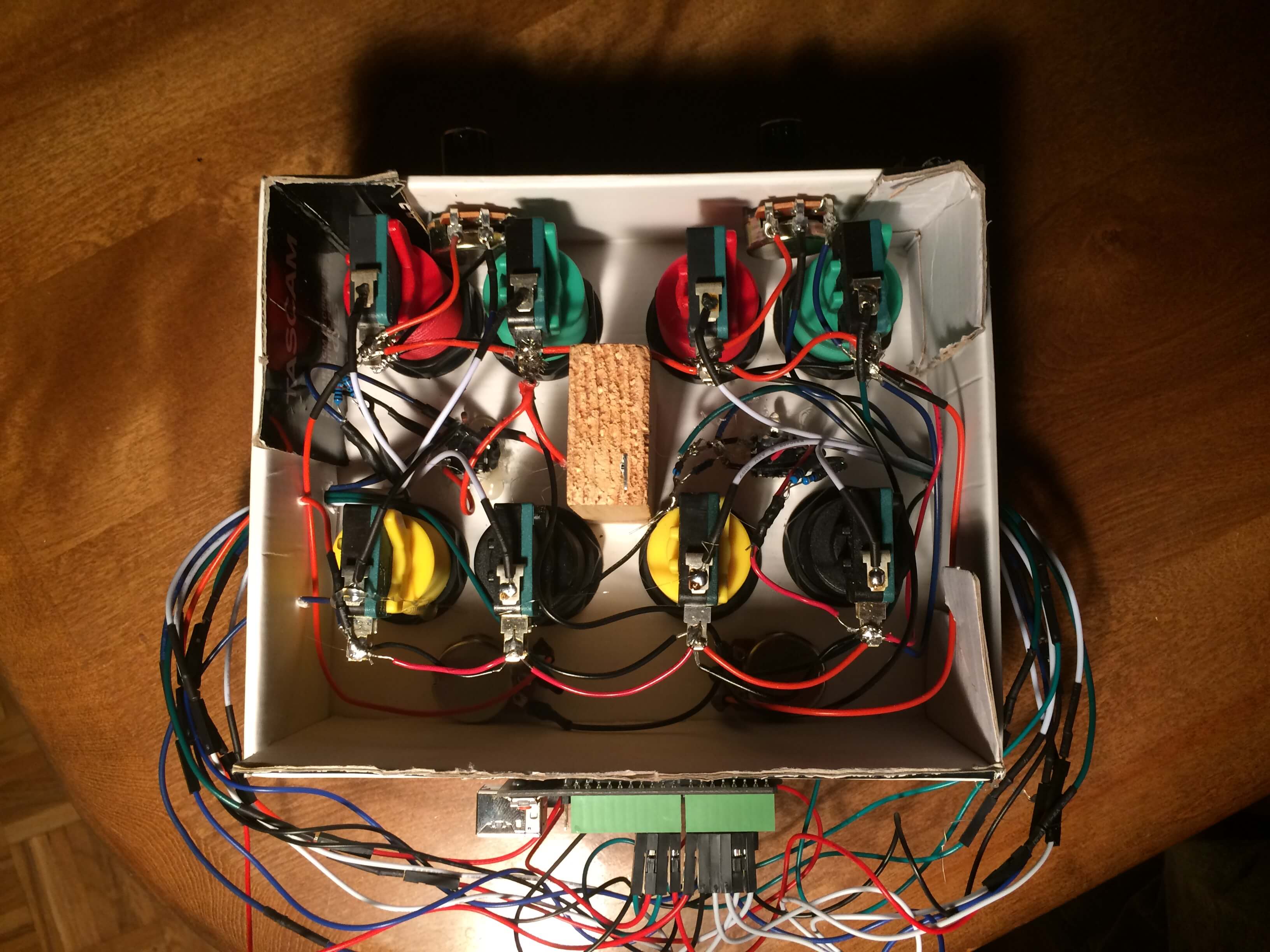
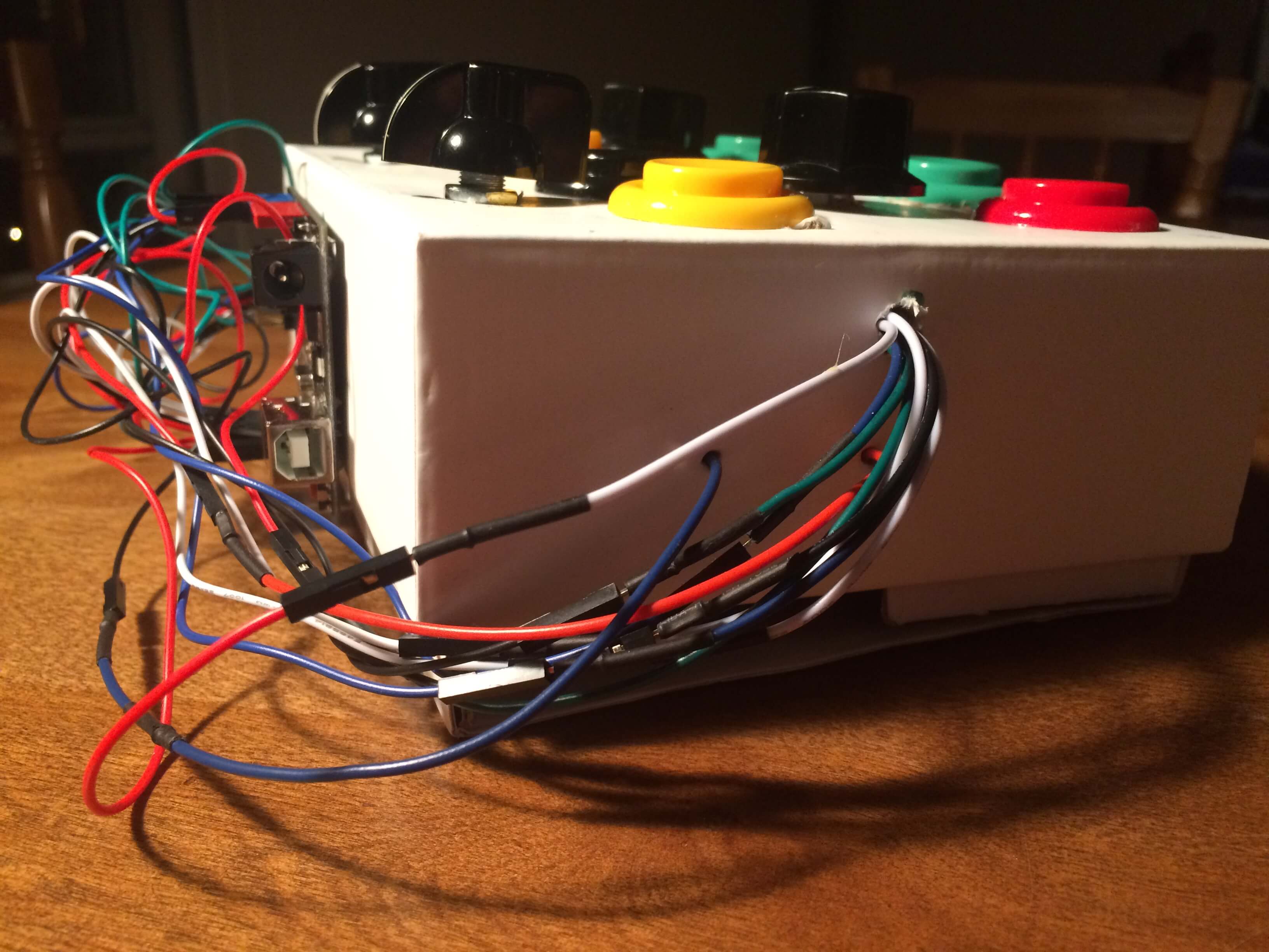
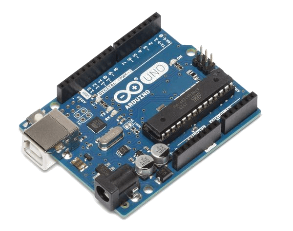
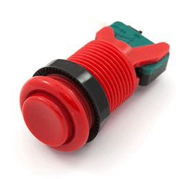
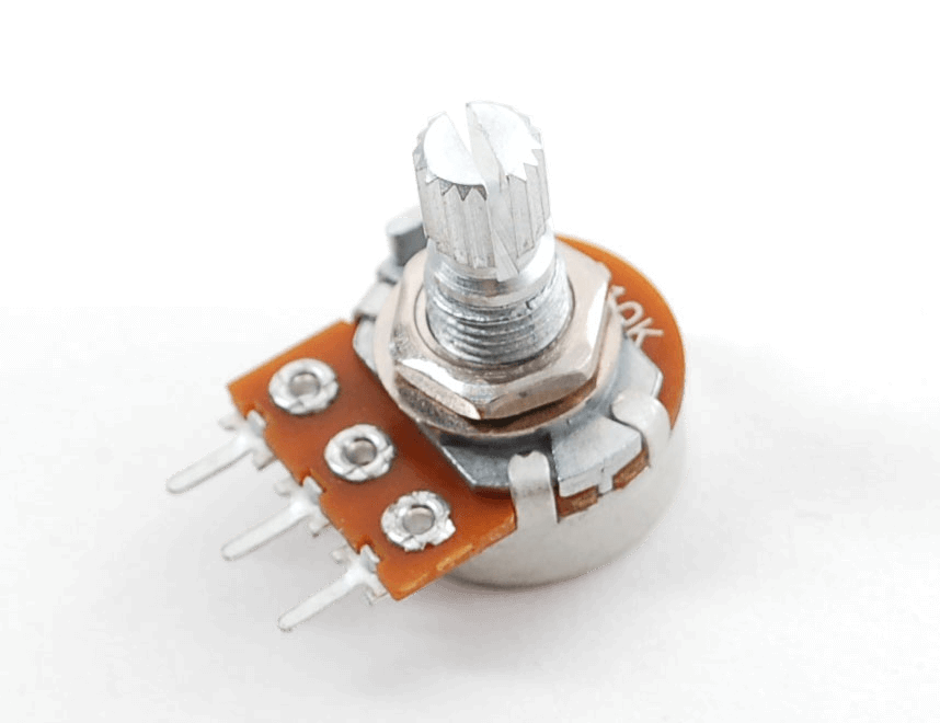
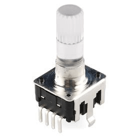
The Candy CTRL is a class compliant USB midi controller built from an Arduino UNO, 8 arcade button, 4 rotary potentiometers, 2 rotary encoders with built in pushbutton switches, and a bunch of poorly soldered wires and resistors. A typical Arduino comes with a number of digital and analog inputs, which allows users to attach sensors which can be easily read to do anything the user might want. In my case, when each sensor is read in, a corresponding midi message is sent back out through the usb cable to a computer. Let's examine the code first.
Programming the Arduino
Arduino CodeDownload the linked code for reference as I'll only be explaining the basic functionality of it. Essentially, I'm storing an array of current and previous values for each of the 14 digital pins and 6 analog pins.
 int digPin[14] = {-1, -1, -1, -1, -1, -1, -1, -1, -1, -1, -1, -1, -1, -1};
 int anaPin[6] = {-1, -1, -1, -1, -1, -1};
 int prevDig[14] = {-1, -1, -1, -1, -1, -1, -1, -1, -1, -1, -1, -1, -1, -1};
 int prevAna[6] = {-1, -1, -1, -1, -1, -1};
Now moving onto the loop, there's two important things we need to check every cycle: the sensor readings, and how they compare to the previous sensor readings. Since each button press corresponds to a noteOn and each release a noteOff, we don't want to repeatedly send extra messages, so some filtering is in order.
 void buttonCheck(){
  // digital edge checks
  for (int i = 2; i < digNum; i++) {
    // on press
    if (digPin[i] && !prevDig[i]) {
      // output note On
      midiSend(MIDI_ON, i+58,100); // noteOn pitch i+58, vel 100, channel 0
    }

    // on release
    else if (!digPin[i] && prevDig[i]) {
      // output note Off
      midiSend(MIDI_OFF, i+58,0); // noteOff pitch i+58, vel 0, channel 0
    }
  }
 }   // DONE BUTTONS

 void potCheck(){
  // iterate through pots
  for (int i = 0; i < anaNum; i++) {

    int temp1 = anaPin[i] /8;
    int temp2 = prevAna[i] /8;
    // if changed value, AND represents a new cc value
    if (temp1 != temp2) {
      // CC at i with the value rounded between 0-127
      midiSend(MIDI_CC,i,127-temp1);  // CC controller i, value 127-temp1, channel 0
    }

    // skip encoders (for now)
    if (i == 1) {
      i += 2;
    }
  }
 }   // DONE POTS
But wait, where are the rotary encoders?
Rotary encoders are peculiar because they sense every time a knob has rotated past a certain point instead of exact position.
Each trigger turns the signal on or off in sequence. Encoders send two separate digital signals for each direction, but as I ran out of digital inputs to use, I had to improvise.
Therefore, both directions of each rotary encoder are being sent to the same analog pin instead. By using two different resistors,
I can measure 4 possibles values for in sequence that reverses when turned in the opposite direction. Since I always know what the next OR previous
value could be, all I need to do is, again, check against the previous value to determine the direction.
Here's an excerpt from the code to interpret this.
 void rotaryCheck(){

  // encoder1   0 512 776 697
  if (anaPin[2] != prevAna[2]) {

    // SCENARIO 1 0
    if (anaPin[2] == 0) {
      if (prevAna[2] > 500 && prevAna[2] < 520) {       // 510
        // forwards
        midiSend(MIDI_CC,2,1);   // CC controller 2, value 1, channel 0
      }
      else if (prevAna[2] > 690 && prevAna[2] < 710) {  // 697
        // backwards
        midiSend(MIDI_CC,2,127);   // CC controller 2, value 127, channel 0
      }
    }
    // SCENARIO 2 512
    else if (anaPin[2] > 500 && anaPin[2] < 520) {
      if (prevAna[2] > 770 && prevAna[2] < 790) {     // 776
        // forwards
       midiSend(MIDI_CC,2,1);   // CC controller 2, value 1, channel 0
      }
      else if (prevAna[2] == 0) {                     // 0
        // backwards
        midiSend(MIDI_CC,2,127);   // CC controller 2, value 127, channel 0
      }
    }
    // SCENARIO 3 776
    // ... and so on for all 4 scenarios, for each encoder
 }
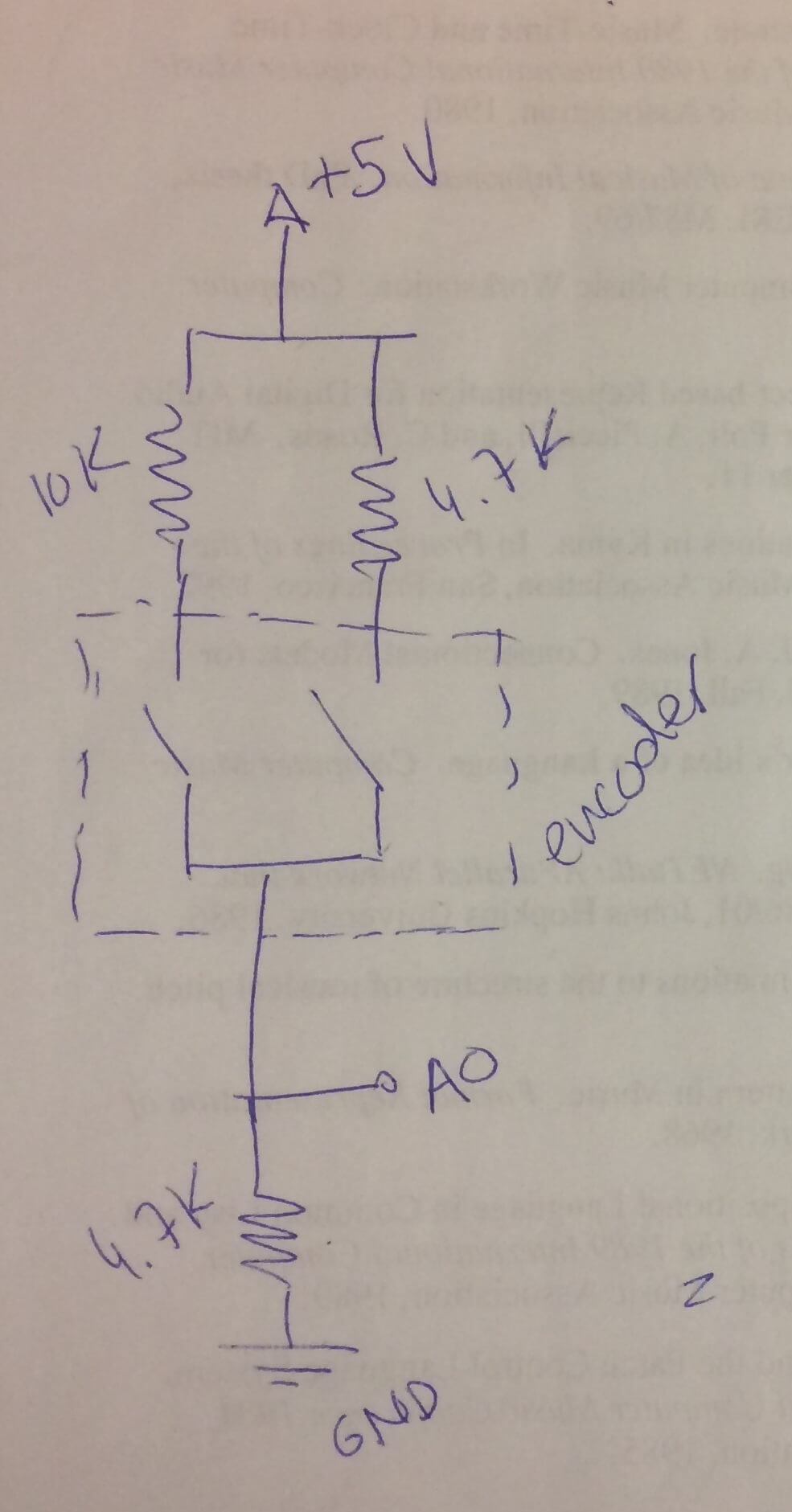
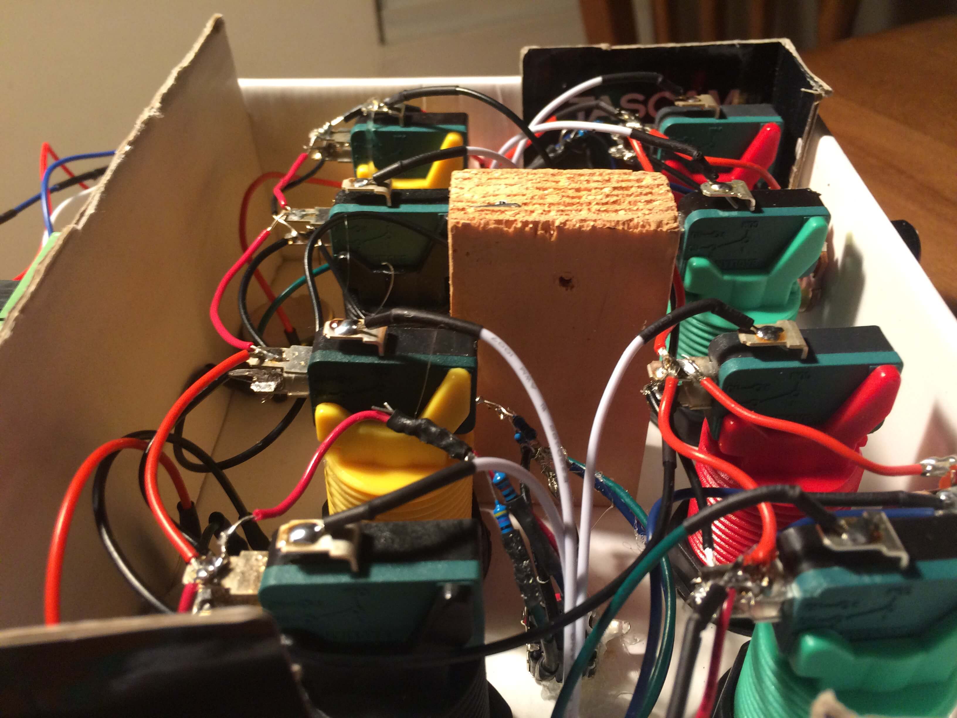
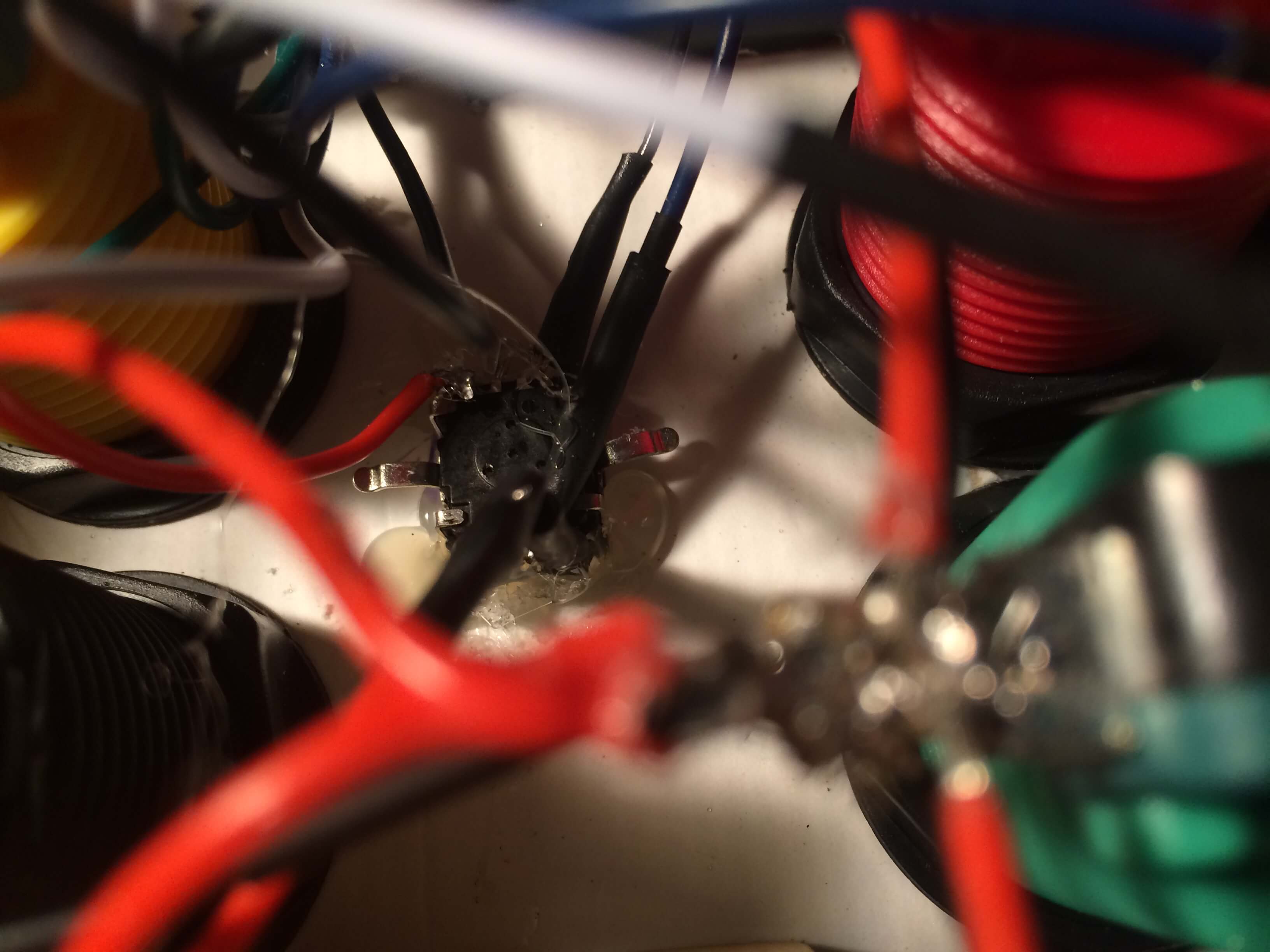
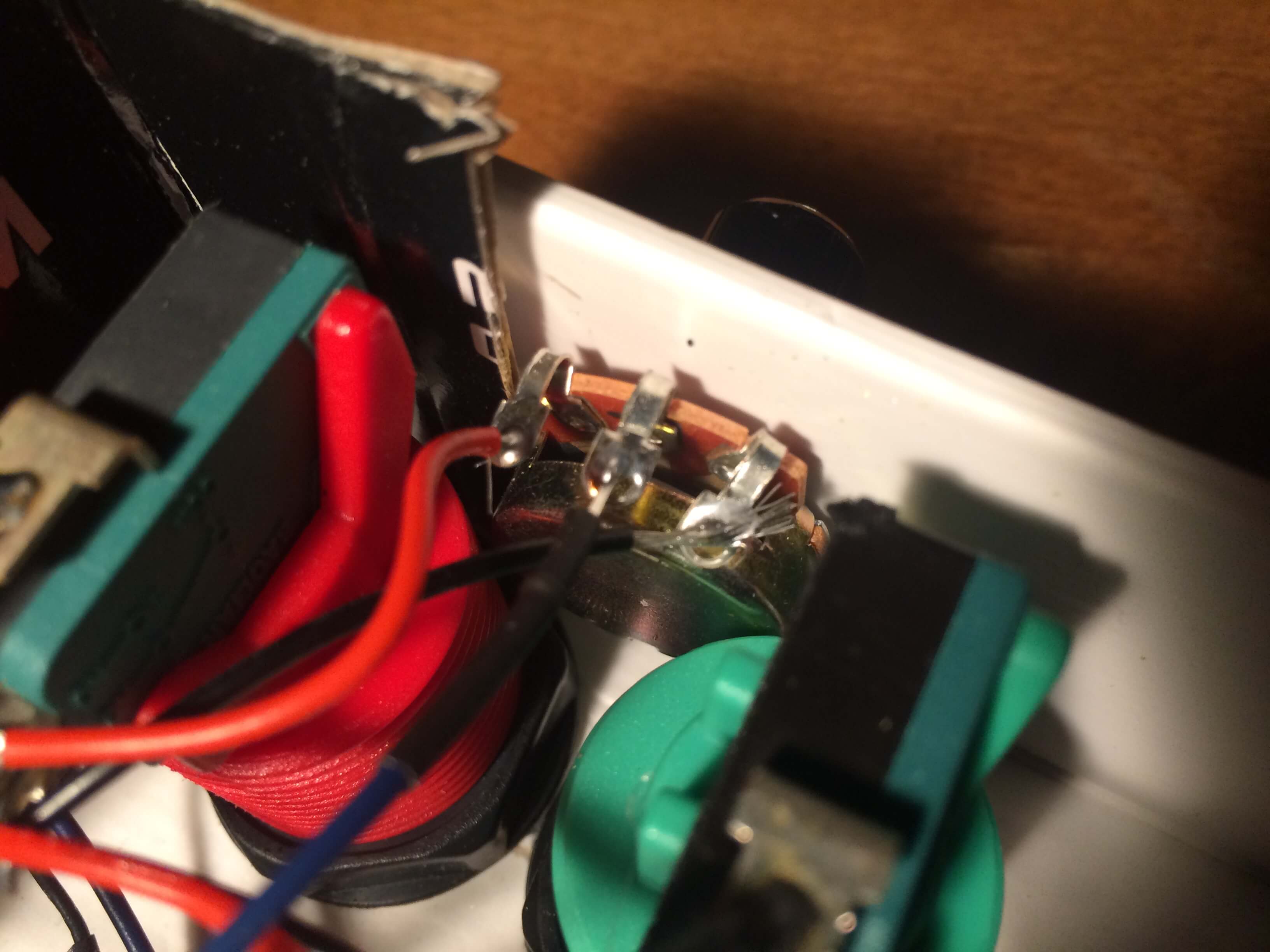
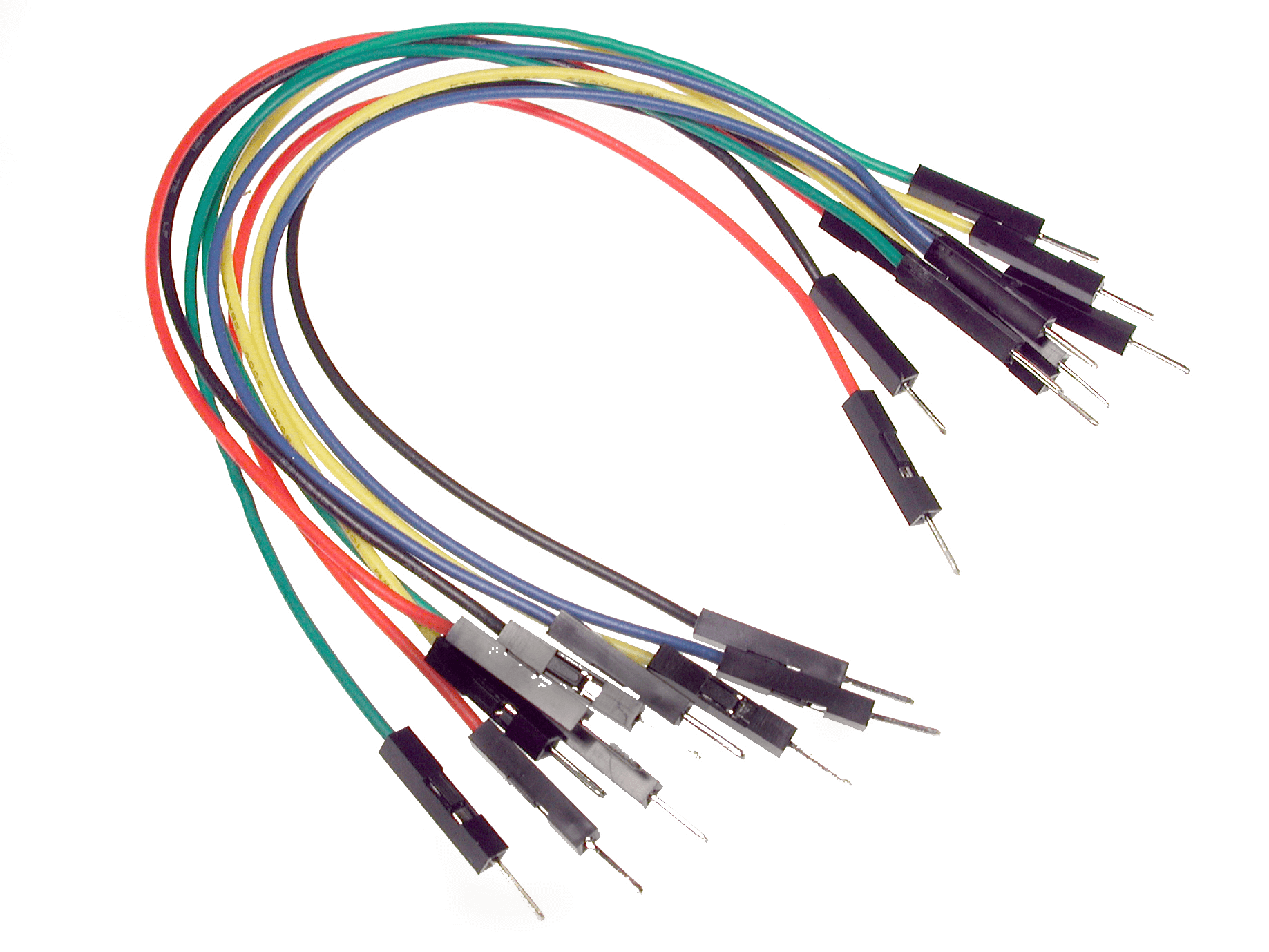
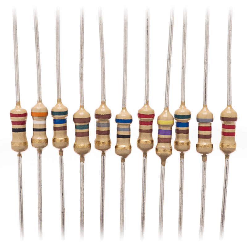
On the right, you can see the wiring that allowed me to use multiple digital sensors on just a single analog pin. Basically, you just need to use different type of resistors for each sensor to ensure that you get a different numerical reading under every possible circumstance. Once you have different numbers reading in, you just need to code a variety of if statements to correlate to each circumstance. In my case, that meant defining a sequence of numbers and then checking both at the current read and previous read to determine which direction through the repeating sequence of numbers we are currently turning. It's possible to do this trick with any digital sensor, as long as the software is able to interpret each event as a separate distinct reading. This also enables nicely bundled wires, since everything will attach to the same pin, power, and ground.
The other interesting thing I did was flash the firmware on my arduino to register it as a generic MIDI device, eliminating the need for extra serial-to-midi converters, like the fantastic Hairless MIDI Bridge. To do this, you need either an AVR-ISP programmer or an extra arduino which can be flashed with the ISP-Programmer software distributed with the Ardunio IDE. Follow this fantastic tutorial here which uses the HIDUINO firmware to emulate a MIDI-USB device. However, once the firmware is changed, the Arduino can no longer be programmed, so make sure your software works before attempting this.
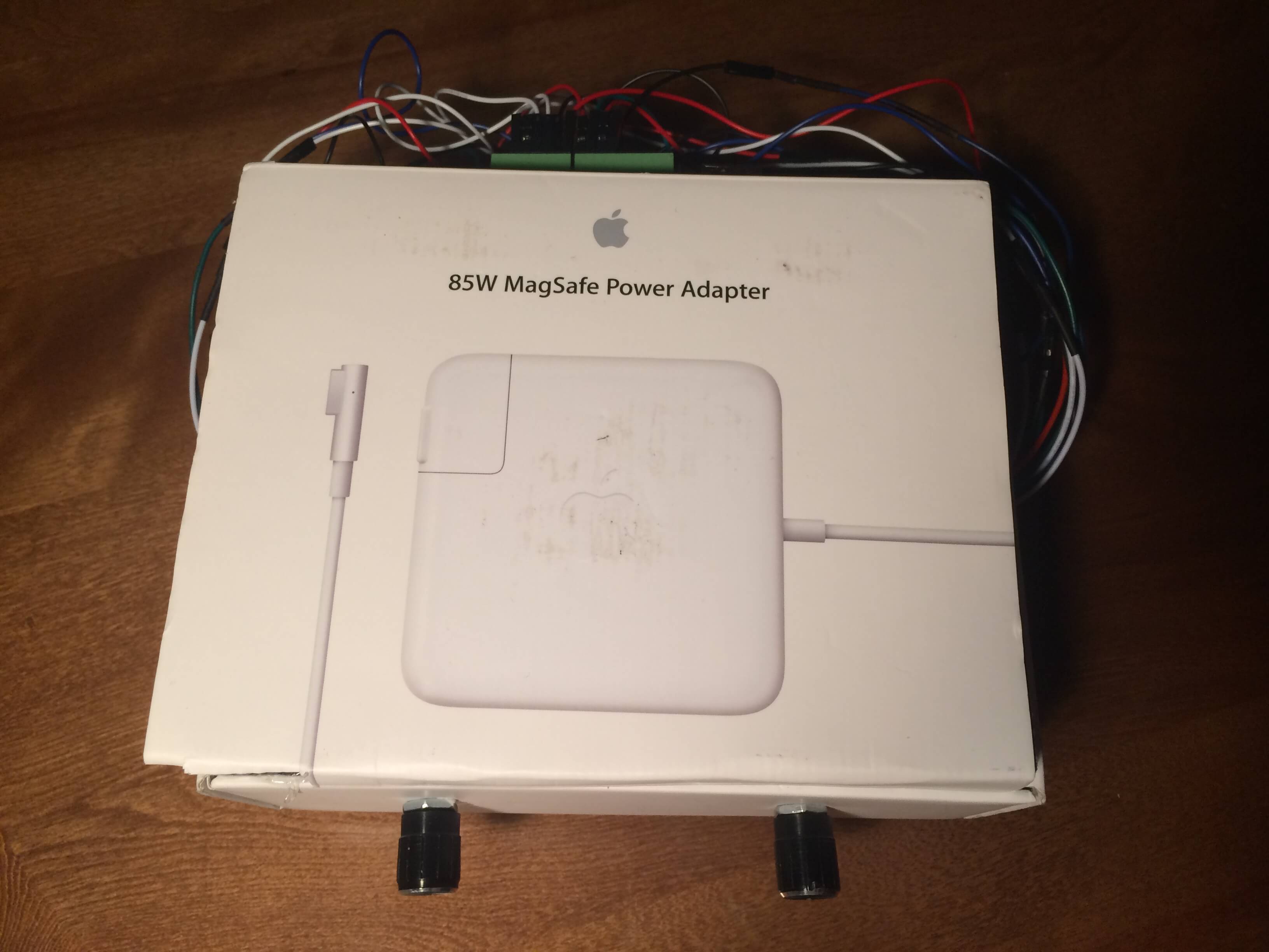
Pictures from Development