Motivations and goals:
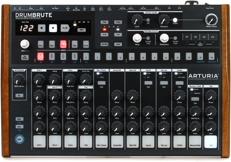
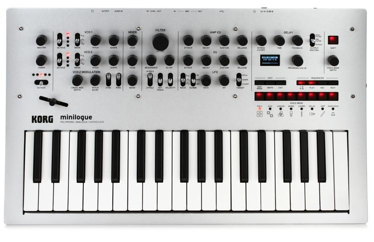
This final project needed to embody multiple of the aspects explored so far in MUMT 306. While this course focussed on algorithmic control and automation, I greatly prefer the immediacy granted by hardware controllers, rather than computer based interfaces. As such, I knew I wanted to incorporate the Arduino board as a means of direct control in the project. Additionally, sequencing has been a large focus in the class and, using inspiration from synthesizers I own (primarily the Arturia Drumbrute, as well as the Korg Minilogue, shown to the right), I decided to create a simple 16 step drum sequencer using the Arduino as a front end for control and input and Max as the backend, sequencing and outputting MIDI data. The following is a list of features I set out to implement:
- 16 Steps
- LED indicators for steps
- Multiple drum instruments
- Kick*
- Snare*
- Clap
- Closed Hi-Hat
- Open Hi-Hat
- Mid Tom*
- Cymbal*
- Cowbell
- BPM control
- Pause and play button, as well as the ability to reset the sequence to the first step
- MIDI output
- "Roller" feature (inspired from the Drumbrute)
- Access to alternate sounds for supported instruments (indicated by an asterisk in the list above)
- Ability to access different kits in SimpleSynth
Outline and Limitations:
The Arduino Uno board boasts 14 digital pins, and 6 analogue pins, with the analogue pins able to double as digital pins, resulting in a total of 20 pins. One caveat is that pins 0 and 1 are used by the board for serial communication, which would be necessary for this project to interface between the Arduino and Max, allowing for only 18 pins. While I wanted 16 buttons as well as 16 LEDs, one per step, this would immediately require 32 pins. In addition, at least one button would be required for each of the following: instrument changes, kit changes, pausing and playing, as well as an analogue pin for the BPM potentiometer, bringing us well above the 18 pins available. The best compromise was the following: 4 buttons would be used to input step events, with another button used to toggle between the groups of steps (1-4, 5-8, 9-12, 13-16), and only 8 LEDs would be used to show the events in the currently selected step group (either 1-8 or 9-16). This cut down the number of pins required to 8 + 4 + 1 + 3 + 1 = 17, leaving us with a single pin as breathing room. Additionally, while the Arduino is a fast board it was decided early on that, to ensure the best reading of physical inputs possible, the Arduino would only be in charge of reading interactions with the controls and relaying the resulting information to Max. Serial communication was also kept at a minimum to ensure fast cycling and increase general efficiency.
Arduino Wiring:
The image on the right shows the final layout of the Arduino board wiring. The Step Group button, the Instrument Toggle, and Kit Toggle buttons all iterate through their respective pool of options. The currently selected step group, instrument, and kit will be printed on the Max console when a change is made. Holding the Instrument Toggle button will toggle the currently selected instrument between its two possible sounds if an alternate is available. The Step Buttons 1-4 will toggle on or off a step event at the selected step (determined by the current step group) for the selected instrument. The Roller was implemented as a ninth instrument, changing the functionality of the Step Buttons. While the Roller instrument is selected, pressing one of the Step Buttons will repeat (from button one to four respectively) the current step at twice the speed, the current step at the set speed, the current and next steps, or the current and next three steps. The steps will repeat as long as the button is pressed, and when released, the sequence will resume from where it would have been had the Roller not been used. The Pause/Play/Reset button will play or pause the sequence, based on the current state. Holding this button will reset the sequence to the first step, but will not change whether the sequence is paused or playing. Lastly, the BPM potentiometer dictates the length of the steps in milliseconds between 100ms and 999ms. This is to avoid ambiguity in "BPM" since the time signature cannot be selected, as well as due to limitations with serial communication. Because the analogue pin's readings are constantly fluctuating and to avoid a steady stream of serial messages, the value read at the potentiometer is only sent to Max when the Step Group buttons is pressed.
All LEDs are attached to the same resistor to save room on the breadboard, although this does have the side effect that, as more LEDs become lit, all lit LEDs will shine more dimly. This is because, while there is 5 V on all activated digital pins, the LEDs only dissipate ~1.8 V, increasing the voltage between the LEDs and the resistor and resulting in a reduced voltage difference between the legs of the LEDs. This could be fixed if all LEDs had their own independent resistor and path to ground. Each button has their lower right leg connected to the 5 V power, their upper left leg connected to a pin, and their lower left leg connected to ground through a pulldown resistor. These resistors are important to avoid a short circuit when the button is pressed, as well as to rigidly define the state of the pin when the button is not pressed. It was important to keep the wiring low-profile for useability, as well as to avoid all possible contact with the pulldown resistors. Touching the pulldown resistors before pressing the button could disrupt the 5 V read at the pin and provide invalid readings.Arduino Code:
The basic structure of the Arduino code consists of the following:
- A double array state[8][16] holds the step information for each instrument in binary. The instruments are ordered in the same order as shown in the Motivations and Goals section(ie state[0][0] gives the kick's first step's state as either 0 or 1)
- Counting flags step_group and instrument keep track of both the step group (between 0-3) and instrument (between 0-8)
- Boolean flags LED_change and other_change keep track of whether a change has been made which requires an update to the LEDs or a change which requires an update to be sent to Max.
- A special flag step_change keeps track of whether a change has been made to the step states. When no change has been made, it is set to -1, and when a a change is made, it is set to the index of the instrument. This ensures that the update about the steps is sent about the correct instrument. Multiple simultaneous button presses could conceivably create a situation where the currently selected instrument and the instrument for which the Arduino must send an update are not the same.
- A function to detect button presses as well as button holding, CheckPress()
- A function to update the LED states, LED()
Button Pressing:
The meat of the Arduino code is in the CheckPress() function. This function handles button pressing, which is a more nuanced problem than it first appears. While the Arduino is able to detect the state of a digital pin as either HIGH or LOW, a button press is not defined by any given state but by a transition between states. The functionality associated to a button can either be assigned to the first transition, which is the press, or the second transition, which is the release. CheckPress() employs two flags, a boolean value pressed and an array of booleans pressed_button[20], where each of the values in the pressed_button array maps to one of the Arduino pins, indicating whether it is currently pressed. The pressed flag limits the number of button presses the code will detect to one, although removing it could allow for button combination for the implementation of additional features. These flags are set upon the detection of a change in state from LOW to HIGH on a button pin, and are removed once the appropriate button is released. The pressed_button array allows for keeping track of which button is pressed, such that pressing another button wouldn't accidentally release the pressed flag. Additionally, a rudimentary "timer" counter is implemented to count the number of Arduino code cycles between a press and a release on certain buttons to detect a "hold" input, which has alternate functions.
CheckPress() also handles button behaviour on a case by case basis, changing state values to modify step events for the appropriate instrument and step, sending out Roller information to Max, changing instrument or step group, etc. Most buttons have their associated response executed immediately upon being pressed, but for buttons with a hold functionality, the response is executed upon the release based on how long the button was held. 5000 cycles was found to be a reasonable number of cycles for pressing a button to be considered holding the button.
Serial Communication:
Information is sent to Max over serial communication. Each message begins with a unique identifier from 0 to 9, 'a', 'b', or 'i', followed by a number of data bytes. 0-7 indicate an instrument step change, and are followed by the 16 binary values corresponding to the step events of that instrument. An exception to this is the alternate sounds message, which consists of the instrument number and a 2 (as this is guaranteed never to be present in the step information messages). 8 indicates a Roller input, and the data ranges between 0 and 4, where 0 is normal play and 1-4 are the four Roller modes as they are represented by the button used to input them. 9 indicates a pause/play/reset message, with data either 0 for pause, 1 for play, or 2 for reset. 'a' indicates a kit change, with no data. 'b' indicates a tempo change, followed by the time in milliseconds. Lastly, 'i' indicates a change in either the step group or instrument, and sends both of these values as the data to Max to be changed to readable text and printed to the console. All bytes are separated by spaces, and all messages end with a newline '\n'.
The Max Patch:
The Max patch is constructed in a modular fashion, with the main patch containing many subpatches that implement specific functionalities.
Arduino_io:
The serial communication in the Max patch is very similar to the one given in class, with the modification that reading a '\n' will send a bang to the zl group object, sending out the list to ensure that all lists are separate no matter their lengths.
Timing:
To ensure that a all step events are triggered simultaneously, a master timing object takes care of both the timing and the counting for all instruments. A single metro object controls the time per step, as dictated by the BPM control from the Arduino. A main counter counts to 16 steps (0-15), while auxiliary counters implement the Roller. These counters only begin counting when receiving the appropriate message, but begin doing so from the current step, while the main counter continues counting as normal. The 2x speed Roller is implemented with an extra metro object, with its argument being half the time given to the main metro. In this way, the counters for the Roller are outside of the normal path and are brought in and out as the Roller is activated. This object takes as input on/off messages, reset messages, and Roller status, and outputs bangs from the metro object, as well as the current step from the counter objects.
Instrument:
The instrument subpatch was implemented so that a single framework could be applied to any of the kit's instrument. Because the difference between drum instruments in MIDI channel 10 is simply the note number, the input argument to the Instrument object (shown as #1 in the default patch) will assign the note to be used in all MIDI messages for that particular instance of the patch. The alternate sounds are also implemented here, with the detection for the instrument change message being implemented with the counter object. The central message boxes store the step event information, which are banged only on the appropriate counter input. A 1 in the step event will trigger a note on MIDI message on channel 10 for the appropriate note with velocity 127. A 0 will send a note off MIDI message on channel 10 for the appropriate note with velocity 0. The patch receives master bang and counter information from the Timing object, as well as the step list, and will output MIDI messages as a list.
Information:
The information subpatch will decode step group, instrument, and kit numbers and map them to human readable text. This information is printed to the Max console when the step group is changed due to pressing the Step Group button, when changing the instrument with the Instrument Toggle button, or when changing kits with the Kit Toggle button.
Summer:
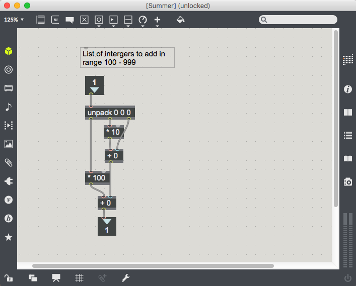
Because the serial communication sends data in bytes, it was found that sending the step time from the BPM control would separate the individual numbers in the total value (resulting in 100 being passed as 1 0 0). The numbers are easy to recombine, as long as the exact length of the value to be reconstructed is know. This required the time per step to be limited to numbers requiring exclusively three digits to write, limiting the range to 100-999. This gives a wide range of useable "tempos", and the Summer subpatch simply implements the reconstruction of these values.
Main patch:
The main patch combines the aforementioned subpatches. Messages are received from Arduino_io (where the port can be selected and serial communication can be turned on and off), routed using the first element of the message and redirected accordingly. Eight Instrument objects implement each of the instruments, all controlled by a single Timing object. The rightmost section implements the kit changing by incrementing through the available kits. These kits are mapped from the SimpleSynth program numbers in the drum section. A message box to the left shows the last message received from the Arduino, and lastly, a single midiout object controls the output of the MIDI messages from the Instrument objects.
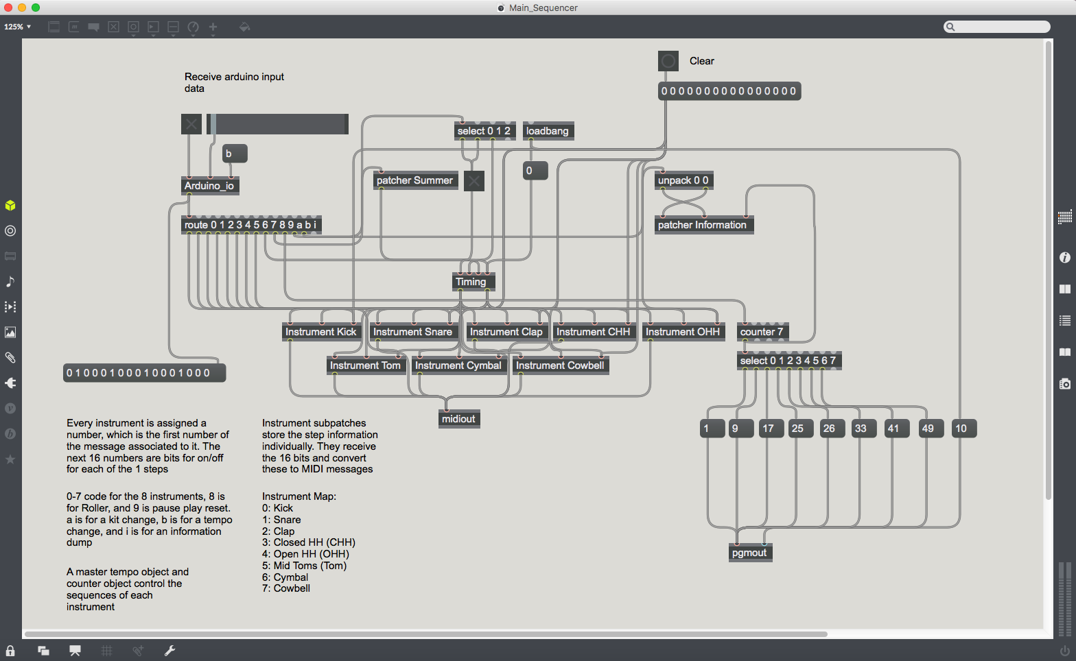
Main Max Patch
Thank you for reading!
Samuel Thibodeau, 260605279, 2018
Arturia Drumbrute
Korg Minilogue
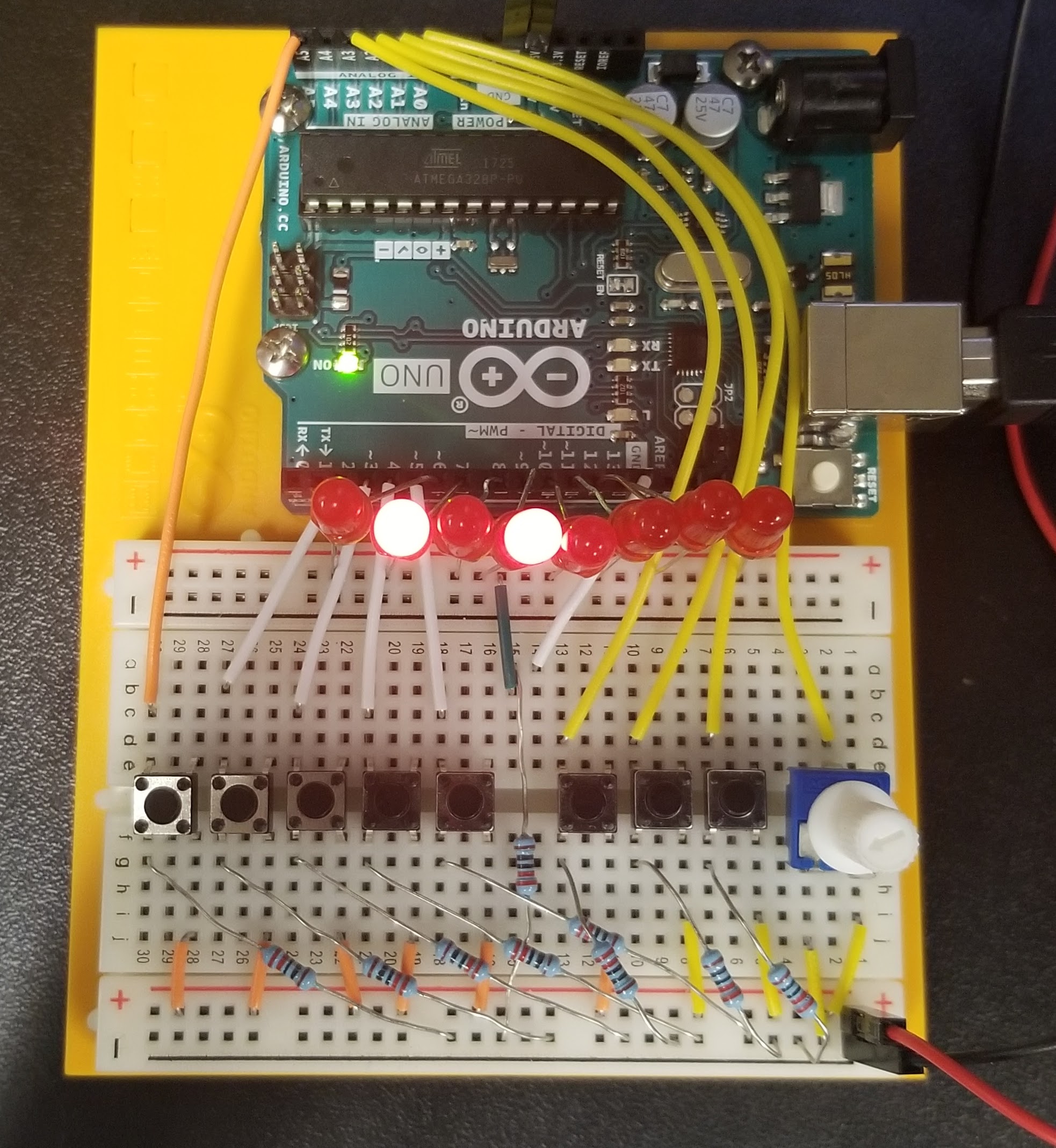
Final Arduino Wiring. From left to right, the buttons are (1) the Step Group, (2-5) Step Buttons 1-4, (6) Pause/Play/Reset, (7) Instrument Toggle, (8) Kit Toggle, (9) BPM Potentiometer
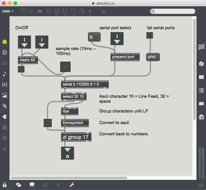
Arduino_io Patch
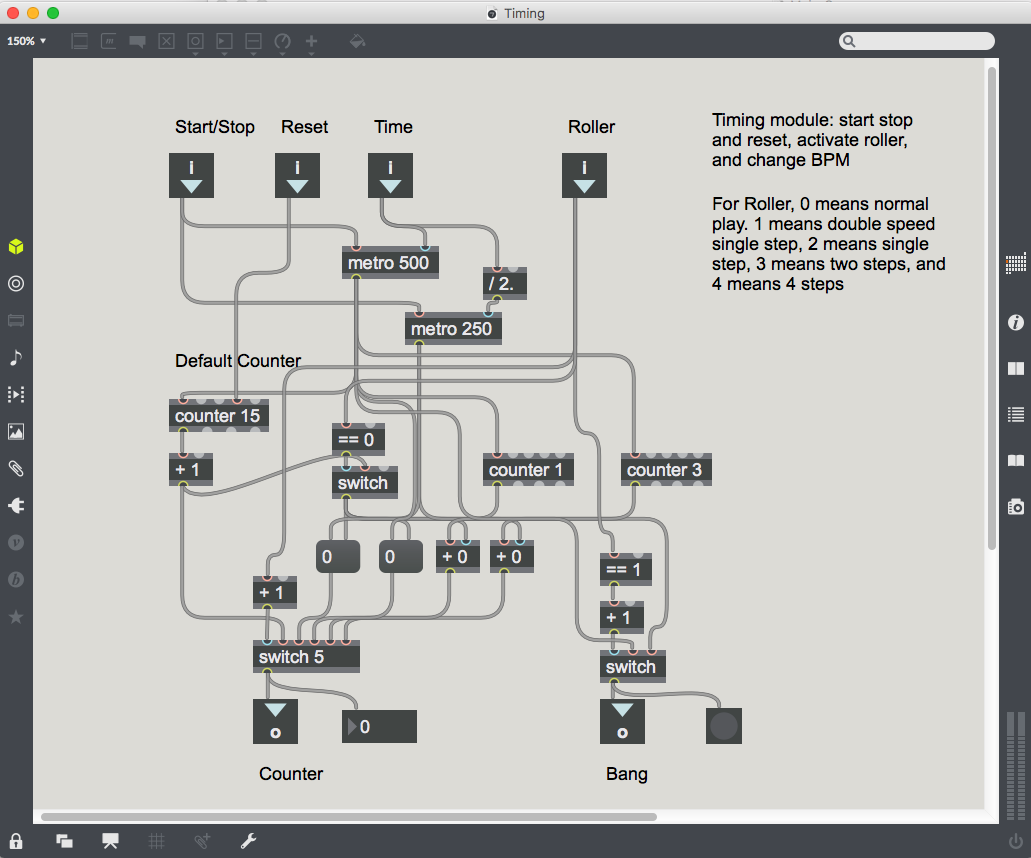
Timing Patch
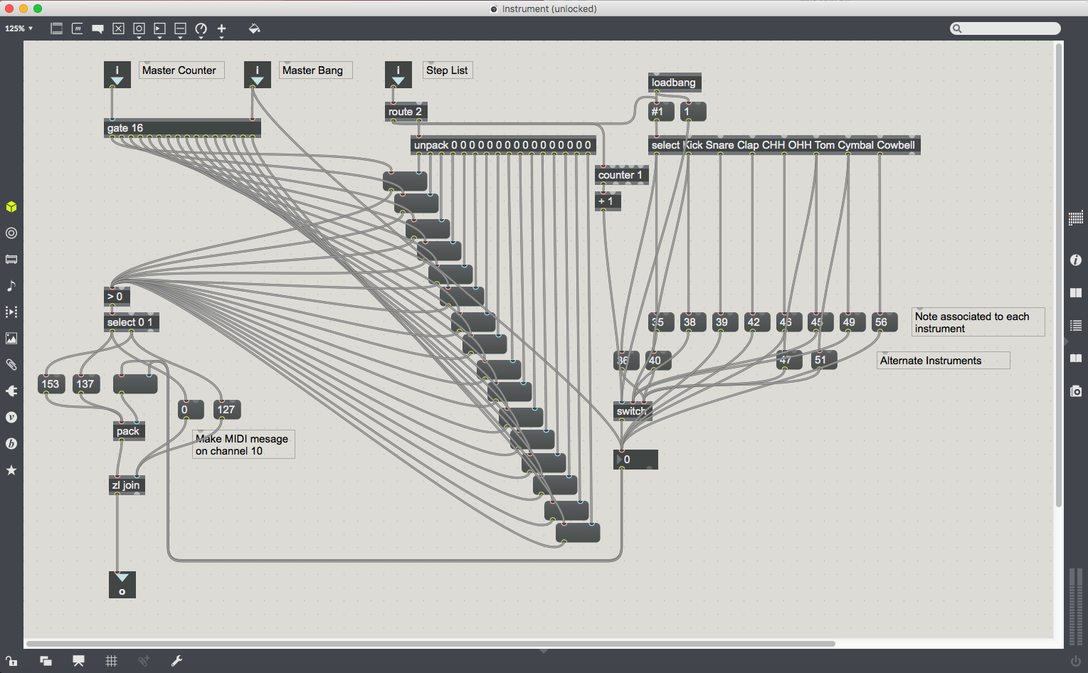
Instrument Patch
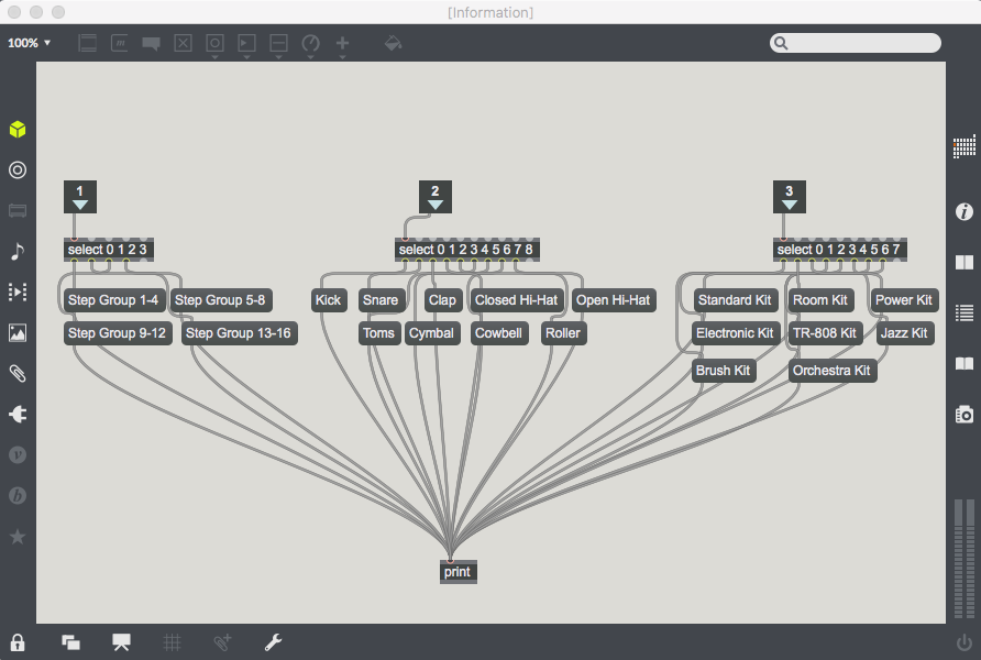
Information Patch
Summer Patch