An Electric Guitar Plucked String Model for
Realtime Control with Distortion and Feedback

Nicholas P. Donaldson
McGill University
MUMT 618 Final Project
Fall 2009


INTRODUCTION
The Karplus-Strong plucked string algorithm, originally published in 1983 (Karplus, Strong 1983) and improved that same year (Jaffe, Smith 1983), provides a simple and computationally efficient method for synthesizing plucked string-like sounds. Methods have been explored for extending this algorithm to simulate the timbre of particular instruments, such as the amplified and distorted electric guitar (Sullivan, 1990). This purpose of this project is to implement a real-time electric guitar synthesis model using many of the extensions proposed by Sullivan, as well as to explore improvements to these extensions and develop a parameterizable control scheme for the synthesis model.


Contents:


Overview

The objectives of this project were to design and implement a digital model of an electric guitar which behaves similarly to a real electric guitar-amplifier system and can be controlled in a useful way in real-time. The synthesis model is designed to simulate the various physical systems comprising an electric guitar setup: the guitar itself (the plucked string), the amplifier (transistor or vacuum tube distortion), and the interactions between the guitar and the amplifier (feedback). Much of the project was designed in MATLAB, and the real-time implementation was written in C++ using
STK and is designed to be controlled via MIDI. Both a monophonic version and a polyphonic version were developed for different methods of control.

The block diagram in Figure 1 illustrates the high-level components in the synthesis model of the polyphonic version of the project. The monophonic version uses just one plucked string generator and has different control parameters, but the synthesis models for the two versions are otherwise the same.


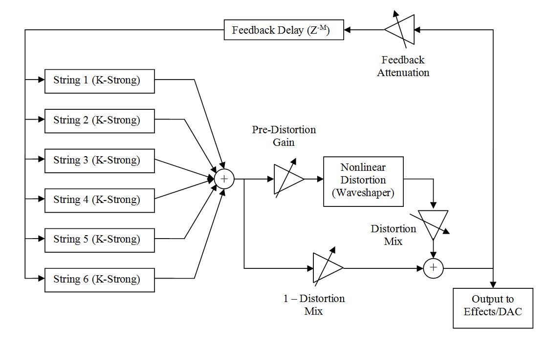
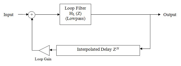
Figure 1: Synthesis Model Block Diagram


The algorithm uses MIDI note on and note off messages to control the initialization of the plucked string generators, which are summed together and passed to the distortion waveshaper, the output of which is combined with the undistorted signal using a specified mix factor. This mixed signal is sent to any effects and then to the output, and is also attenuated and sent back to the string generators to simulate feedback from the guitar amplifier to the strings. The parameters for distortion, feedback, timbre, and effects are all controlled in real-time with MIDI control messages. The individual parts of the algorithm will be described in detail in the rest of this report.

Back to Contents


The Plucked String

The basis for the plucked string model is the Karplus-Strong algorithm [
1] with extensions proposed by Jaffe and Smith [2] for better control over tuning precision, decay rate, dynamics, and harmonics present in the string (pick or pickup position). Further extensions proposed by Sullivan [3] for improved loop filtering and DC removal were also implemented. A brief explanation of Karplus-Strong algorithm and the aforementioned extensions will be provided here. For a detailed analysis, please see the article by Jaffe and Smith [2].


Figure 2: The Basic Karplus Strong Loop with Input for Feedback


The basic Karplus-Strong plucked string loop consists of a delay line of N samples, initialized to be the length of one period of the desired fundamental frequency fo at the sample rate fs:

N = fs/fo


The loop filter HL(Z) has a monotonically decreasing lowpass frequency response, ideally with linear phase and unity gain at fo. The original filter choice was a first-order FIR filter with each coefficient equal to 0.5:

HL(Z) = 0.5 + 0.5z-1


This filter has both linear phase and a monotonically decreasing lowpass frequency response, but does not account for changes in fo and thus results in different harmonic decay rates for different notes, a less-than-desirable characteristic which will be addressed later.

At the start of a note, the delay line is filled with noise from a random number generator, which can be scaled to an arbitrary maximum value to change the resulting amplitude of the pluck. The noise, which contains energy spread out across a wide range of frequencies within the Nyquist rate, will be filtered by the lowpass filter so that the higher frequencies are attenuated faster than the lower frequencies with every cycle of the loop. Additionally, as shown in the article by Jaffe and Smith [2], with each iteration of the loop, frequencies with period lengths that do not have integer multiples near the entire loop delay length will be attenuated due to self interference. This is analogous to the way energy which is put into a string fixed at both ends will quickly form harmonic standing waves. Because of the lowpass filter, the resulting quasi-harmonic signal experiences a string-like frequency dependent decay where the higher harmonics decay faster than the lower ones.

Finally, he initial harmonic content of the pluck may be altered by repeatedly lowpass-filtering the initial noise burst any desired number of times [3], effectively reducing the "brightness" by reducing the high-frequency content of the noise burst before putting it into the delay line. This is loosely analogous to changing the hardness of the picking mechanism (plectrum or finger) when playing an electric guitar

This general model, though efficient and effective, has many undesirable characteristics, which will be discussed and improved the following sections.

Back to Contents


Tuning

The original Karplus-Strong algorithm uses an integer-length delay line to represent the period of the fundamental frequency, so the precise required delay length is only achieved for fundamental frequencies which are integer divisions of the sample rate. This model works relatively well for low pitches, where there are larger differences in the delay line lengths for neighboring semitones and the pitch errors are less noticeable. However, for higher pitches, there are much smaller differences in sample lengths between neighboring semitones, and the tuning problem becomes obvious.

A solution for more precise tuning proposed by Jaffe and Smith [
2], which is the method implemented in this project, is to use an all-pass interpolated delay line for achieving fractional sample delays. The first-order allpass filter has the transfer function:

Where for a fractional delay of approximately 
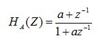
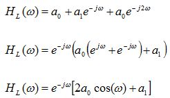
samples, the coefficient a is given by:


However, as seen in the following graph taken from that paper, while the magnitude response of the allpass filter is flat across all frequencies, the phase delay is frequency dependent. Although the delay is approximately linear for low frequencies with fractional delays between approximately 0.3 and 1.3 samples, it becomes very non-linear for higher frequencies or fractional delays outside of that range.


Figure 3: Allpass Interpolation Sample Delays vs. Frequency [2]

In the Karplus-Strong algorithm, this filter is placed at the end of the delay line and parameterized for the proper fractional sample delay. This leads to accurate tuning and well-perceived pitch for lower notes, whose higher harmonics do not extend much into the non-linear frequency range of the allpass interpolation filter. For higher notes, the phase delay of the harmonics is not linear with respect to the fundamental, resulting in perceived pitch which often sounds "flat" or lower than expected.

The solution to the problem of perceived pitch may be solved by simply manually tuning the fundamental frequencies of the notes to produce the desired "in-tune" sounding pitches. This can be done experimentally and can easily be implemented as a look-up table for all notes which contains the corresponding in-tune-sounding fundamental frequencies. Although it would have been a useful addition to this project, there was not enough time to perform the tedious task of tuning each note. In general, it should be noted that all but the very high notes sound reasonably well-tuned with other nearby pitches, so the tuning problem only becomes noticeable when playing with other instruments or when playing across multiple octaves.

One final condition for precise tuning is that the lowpass loop filter adds a non-negligible amount of delay to the loop, as shown in the discussion of the loop filter. This delay must be compensated by subtracting the filter delay from the delay line length.

Back to Contents

Pitch Bends

One of the most expressive features of the electric guitar is the ability to create pitch bends or vibrato by simply using one's finger to stretch the string. Obviously, to simulate these kinds of effects, it is necessary to synthesize a continuous range of fundamental frequencies outside of the quantized equal temperament 12-tone scale. In his article on extending the Karplus Strong algorithm for electric guitar synthesis, Sullivan [
3] suggests the use of a linear interpolating filter for the purposes of both precise tuning and smooth pitch bends and glissandi.

For a fractional delay of 
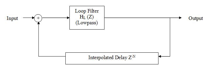
samples, this filter has a transfer function given by:


Sullivan suggests the use of this filter for delay line interpolation rather than the allpass method due to the fact that a continuous ramping of the coefficients by changing 
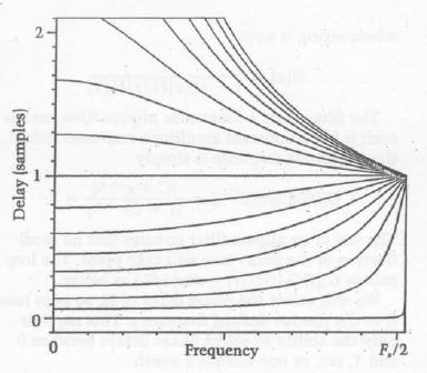
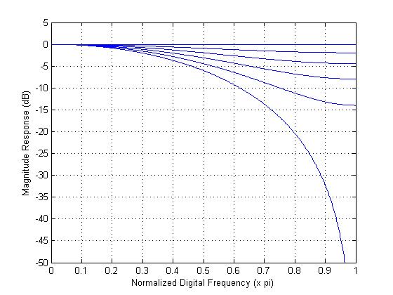
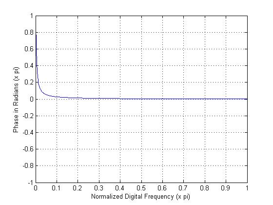
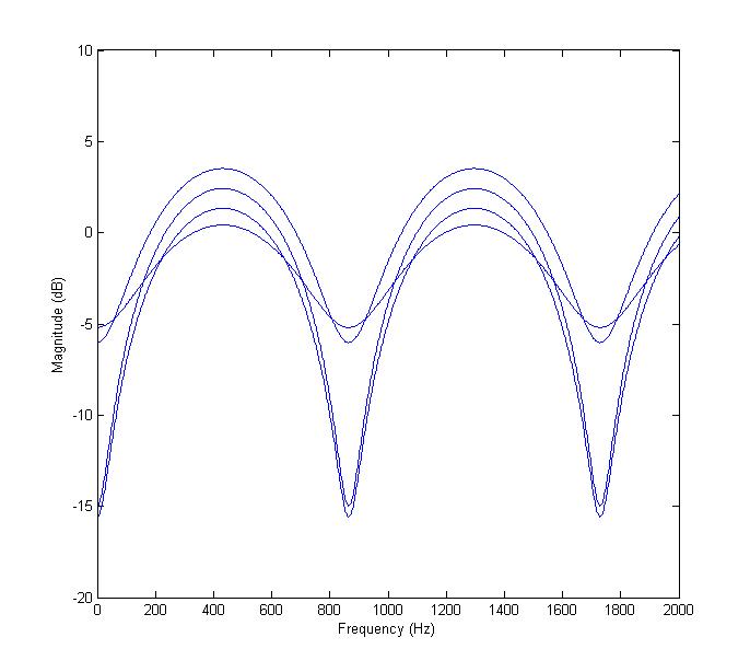
results in a smooth and continuous change in the delay line length, because setting = 1 is equivalent to simply extending the delay line by one sample. This is not the case in the allpass filter, where care must be taken to ensure that the coefficient is within an acceptable range of values for near-linear phase response ( between 0.3-1.3). In the case of smooth delay line length changes, as in pitch bends, he suggests that this would result in audible "clicks" when the coefficient must suddenly jump down or up to satisfy this threshold.

Although Sullivan's argument is valid, there is one aspect of the linear interpolation filter which makes it rather undesirable for plucked string simulation: the magnitude response of the filter is not flat over all frequencies, and changes with (Figure 4). Take for example the case where = 0.5, and we have a transfer function identical to the original Karplus Strong loop filter. In this case, and any case for not equal to zero or one, the interpolating filter is lowpass in character, which means that the higher frequencies in the plucked string signal will be attenuated depending on the desired delay line length.
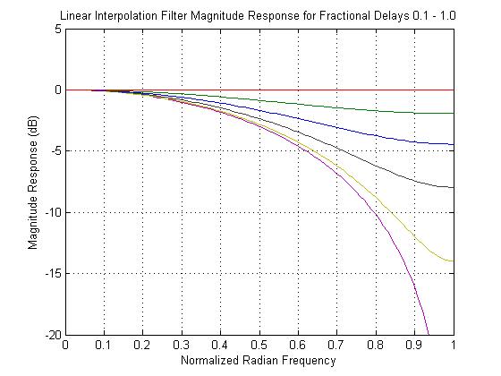

Figure 4: Linear Interpolation Magnitude Responses


To implement pitch bends and vibrato, the model developed in this project uses allpass-interpolated delay lines, varied either sinusoidally (vibrato) or linearly (pitch bend) with respect to perceived pitch. Because perceived pitch is non-linear in frequency, the standard 12-tone equal-temperament formula is used to evaluate frequencies for these pitch bends:


Where n is the number of equally-tempered semitones to shift the base frequency fb, and n can be positive or negative and take fractional values.

To implement a dynamic pitch bend, the base frequency of a given note is saved in memory, and the instantaneous "bent" frequency is calculated by sampling the MIDI pitch wheel, converting the sample to be continuous in the range -1 to +1, and multiplying by a constant "bend range" in semitones to calculate n for the above formula. The bend range may arbitrarily chosen or parameterized for real-time adjustment, and may be different for positive and negative pitch bends if desired.

To implement vibrato, the same method is used, and the instantaneous frequency is calculated by multiplying a low-frequency sinusoid by a constant "vibrato depth" to obtain n. The amplitude of the sinusoid is controlled by the MIDI modulation wheel controller. Due to the fact that a guitar player creates vibrato by stretching the string with his or her finger, the base pitch of a note can only increase when vibrato is performed on a real guitar. To simulate this, the sinusoid is made positive-only by adding a DC offset of 1 before scaling it. Other low-frequency waveforms such as a triangle or rectified sine wave could easily be implemented for vibrato as well.

Consistent with Sullivan's analysis, even with very smooth bend, the allpass filter causes very subtle discontinuities to be heard as the delay line length changes. These discontinuities are not obvious enough to justify choosing the linear interpolation approach, which was also tested and caused very noticeable high-frequency attenuation and made notes decay quickly.

It should also be noted that for a smooth MIDI-driven pitch bend to occur over large pitch ranges, the pitch bend wheel must be sampled at a fast enough rate to avoid noticeable jumps in the pitch between updates. In the implementation of this project, the pitch bend wheel is only sampled while the audio buffer is being filled, so to achieve smooth pitch bends the buffer size must be as small as possible for the host computer so that the routine spends little time idling between periods of filling the buffer.

Back to Contents

The Loop Filter

The filter in the Karplus-Strong loop, which causes the string-like decay of higher harmonics faster than lower ones, has a few desirable characteristics. Firstly, it should have a linear phase response so that the harmonics remain aligned in time and we avoid issues of perceived pitch and tuning as discussed previously. Furthermore, the filter's magnitude response should be adjustable in real time so that we can ensure that the higher notes do not decay faster than lower ones by an undesirable amount.

Any symmetric FIR lowpass filter satisfies the general linear phase requirement, and the 2nd-order filter proposed by Sullivan [
3] is easily parameterizable for dynamic control as well.

This filter has a transfer function equal to:


We can calculate the frequency response of this filter by replacing the unit delays z with :


The exponential term in the above expression represents the phase response, while the absolute value of the term in brackets is the magnitude response. Because is equivalent to a unit delay in the discrete-time domain, the approximate delay through the filter is constant and equal to 1 sample over all frequencies, which should be subtracted from the delay line length to preserve precise tuning.

The condition for monotonically decreasing lowpass response is given by Sullivan as:


This is easily verified by noting that for a1 < 2a0, the magnitude response term in brackets goes negative in the digital frequency range (0,pi), which would result in a zero at that point followed by a magnitude increase.

The 2nd order FIR filter with this condition proves to be a useful choice for the loop filter. It is easy to parameterize the filter coefficients to be adjustable in real time over the full range of monotonically decreasing magnitude responses (Figure 5). The filter response can be adjusted in real time, meaning that the decay time of the higher harmonics in any given note can be modified. This effectively solves the problem of the higher notes decaying very quickly, as is the case with the use of a fixed filter.


Figure 5: Response of 2nd-Order FIR Loop Filter for Various Choices of a0


This filter could also be used in a parameterization scheme where the fundamental frequency of the note automatically controls the filter response for changes in timbre and decay times of higher notes. There was not time to develop and fine-tune such a scheme for this project, but the filter can be controlled manually in real-time by a MIDI control change number.


Figure 6: Karplus-Strong Loop with Gain Factor


In addition to frequency dependent decay of the plucked string signal, the overall decay of the signal - including the fundamental frequency - may be controlled by introducing a gain factor slightly less than one within the loop, as shown in Figure 6. In the implementation presented for this project, this decay is kept close to 1 when a note is played, and set lower when the note is released so the note decays quickly when released, regardless of pitch. Both the note-on and note-off loop gain levels are adjustable in real-time for adding damping or sustain effects.

Finally, Sullivan [3] also points out the necessity of handling any DC content which may be present in the initial noise used to fill the delay line. The loop filter has unity gain at DC, and having DC content in the loop or in the plucked string signal may cause problems if it grows. For example, if the feedback implemented at the input of the loop also contains a DC element, it is possible that there will be a growing DC offset that leads to clipping. Sullivan suggests the use of a one-pole, one-zero DC-Blocking high pass filter within the loop:


However, this filter has a very non-linear phase response:


Figure 7: Phase Response of DC-Blocking Filter for 60 Hz Cutoff at fs = 44.1 KHz


The non-linear phase response of the proposed DC blocking filter was seen to have the same effect as the delay line interpolating filters. It changes the relationships of the harmonics within the note, and causes the perceived pitch to go out of tune.

The method for eliminating DC content used in this project, which is briefly mentioned in the Sullivan article [3], is to calculate and subtract the mean value of the noise burst before putting it in the delay line. Additionally, a similar DC-blocking filter to the one suggested by Sullivan is applied to the feedback before it is added back into the loop, to remove any DC content added by the distortion waveshaper, in which case the non-linear phase response does not matter due to the theory behind the feedback system, as will be explored later.

Back to Contents

Pickup Filter

In a real electric guitar, the placement of the pickups has a significant effect on the harmonic content and timbre of the signal sent to the amplifier.

Take for example an open, un-fretted guitar string of length L with a pickup placed at L/8 the distance from the bridge (not to scale):


Figure 8: Un-fretted String with Pickup


As standing waves form, with period lengths that fit into L, any standing wave component with an anti-node at L/8 will not be "seen" by the pickup. In this case, any harmonics which are integer multiples of 8 will be attenuated in the output from the pickup.

In general, for a pickup placed L/N from one end of a string of length L, any harmonics which are integer multiples of N will have anti-nodes at the pickup position, for N = 2,3,4....

Jaffe and Smith [
2] point out that the use of a properly parameterized feedforward comb filter applied to the initial noise burst will introduce zeros in the resulting note spectrum consistent with plucking the string at different points along its length, including antinodes of harmonic components. The same principle can be applied at the output of the karplus strong loop to simulate the pickup position, where the pickup attenuates any harmonic which has an antinode above the pickup.

The feedforward comb filter has the difference equation:


Where mu is the fractional length of the string where the pickup is placed, N is the equivalent length of the string in samples, and a is a "mix" variable ranging from 0 to 1 which controls the maximum attenuation and depth of the notches introduced to the spectrum, by changing the proximity to the unit circle of the equally-spaced zeros in the transfer function. The mix factor a may be considered somewhat analogous to the closeness of the pickup to the string.

It can be shown that fretting different points on the same string will not change the effect of the comb filter for simulating a given pickup position. This implies that for a given string the filter settings may remain constant for any note. To illustrate this concept, consider as an example the "A" string of a guitar, which has an un-fretted fundamental frequency of 110 Hz. Using the above difference equation to set the comb filter for a pickup at 1/8 the virtual "length" of the string away from the bridge results in reduction of magnitude for all harmonics which are multiples of 8 (880 Hz, 1760 Hz, etc.) as seen in Figure 9.


Figure 9: "A" String Comb Filter Response for Pickup at L/8 and Various Mix Levels


Consider now the case where the string is fretted at the twelfth fret, cutting its length in half and raising the fundamental frequency to 220 Hz. The effective pickup position is now also cut in half, since its distance from the bridge has not changed and the string is half as long. The notches in the spectrum will correspond to harmonics of 220 Hz which are divisible by 4 - the same frequencies as before (880 Hz, 1760 Hz, etc.). The same is true for any other "fretted" note, so the pickup filter settings can be left constant for a given virtual string.

The addition of the pickup comb filter at the output of the extended Karplus-Strong algorithm was implemented in this project, and worked well to produce realistic-sounding and adjustable electric guitar timbral effects. However, for this pickup position model to be truly consistent with a real guitar, the pickup position should affect each virtual string in a polyphonic simulation differently based on its un-fretted or "open" fundamental frequency. Given the fact that many of the same notes can be played on multiple strings of a guitar, it would be necessary to pre-determine which note corresponds to which virtual string to incorporate this information into a keyboard-controlled polyphonic model. Because of this control limitation, the pickup comb filters in the polyphonic and monophonic implementations of the project are always parameterized for an open string fundamental frequency corresponding to the low-E string of a guitar, which has a fundamental frequency of about 82 Hz. The pickup position and mix factors can be adjusted in real time, and the position can be chosen to up to half the "length" of the string. The gain greater than one introduced by the filter, as can be seen in Figure 9 is calculated by taking the sum of the comb filter coefficients, which is equal to (1 + a). The input to the filter is scaled by the inverse of this amount to compensate and ensure the loop gain is less than or equal to unity.

Back to Contents


Distortion

One of the most important contributions to the tone of the electric guitar is the method by which the signals from the guitar pickup are amplified. Many guitarists create a harmonically-rich distorted tone by increasing the gain of the amplifier to a point where the amplification circuit elements (transistors or vacuum tubes) begin to exhibit non-linear behavior.

The non-linear characteristics of guitar amplifiers may be time-dependent and very complex to derive. In basic digital simulations, distortion is often implemented by using waveshaping techniques, where a non-linear function is applied to a signal one sample at a time. Nonlinear waveshaping functions may be experimentally derived to simulate the behavior of a specific amplifier system, many of which have time-varying distortion characteristics [
4], but some of the most basic and easy to implement are static hard and soft clip nonlinearities [3], where the peak level of the signal is restricted to some maximum value and a series of harmonics develops.


Hard Clip Distortion Function (Sullivan)


Soft Clip Distortion Function (Sullivan)

The hard-clip function roughly approximates the behavior of transistors in solid-state amplifiers when the input signal amplitude is too high and the maximum allowable "swing" level is exceeded, resulting in the output being clipped to the supply voltage [6]. The soft-clip function roughly approximates the behavior of an over-driven vacuum tube amplifier, if the distortion is considered symmetric for positive and negative signals. Because the output will be limited to the range of -1 to 1, a large amount of gain can be applied to the input of these functions, which will change the harmonic content at the output.

Although the mathematics behind waveshaping functions and nonlinear distortions tends to be very complex, especially for non-harmonic inputs, we can approximate the effects by using sinusoidal inputs. The square-wave-like clipping effects of these two waveshaping functions can be approximated by the fourier series expansion of a periodic square wave of fundamental frequency f:


For a sinusoidal input, as the input amplitude increases beyond the clipping point, the clipped sinusoid begins to resemble a square wave with the same fundamental frequency (Figure 10 (b)). As the fourier expansion shows, this is equivalent to adding infinite odd harmonics at decreasing amplitudes, which is a simplistic approximation of the harmonic content added to the input signal as a result of the clipping.


Figure 10: Outputs of Hard, Soft, and Asymmetric Distortion Functions for a Sinusoidal Input
(a) Undistorted 110 Hz Sine, (b) Hard Clip, (c) Soft Clip,
(d) Asymmetric Soft Clip (input magnitude scaled to 1)


For input amplitudes less than one, the soft-clip function is simply a third-order polynomial. This results in the addition of energy at the third harmonic for lower amplitude inputs [5], which enriches the tone a small amount without the heavily-distorted effects of clipping. This can be shown by expanding the soft-clip polynomial for a zero-phase sinusoidal input using the Binomial formula:


Following this method of expansion, it can be shown that any polynomial waveshaper with a sinusoidal input adds harmonic content depending on the order of each monomial term. The harmonic content added for each monomial term will be even harmonics from DC to the order of the term for even-order monomials, and odd harmonics from the fundamental to the order of the term for odd monomials.

Also implemented in this project is the asymmetric distortion function shown below (found in Pakarinen-Yeh's article [4] with origins from a patent held by Doidec et al. 1998). This function clips the positive portion of the wave at a relatively low input level, while the negative portion of the wave is very softly clipped (Figure 10, Figure 11). This asymmetry somewhat approximates the duty-cycle modulation seen in overdriven tube amplifiers, where the clipping is applied to the wave on a non-50% duty cycle [5][6]. The asymmetric clipping adds even harmonics as well as odd harmonics, resulting in a richer tone unique to tube amps.


Asymmetric Distortion Function (Pakarinen, Yeh)


In the implementation developed for this project, the asymmetric function produces the richest and best-sounding distorted electric guitar timbres of the three, but it also adds energy at DC due to the asymmetry, which is filtered out before being fed back to the Karplus-Strong loops to avoid any potential for a growing DC offset. The clip condition for input values less than -1 was added to restrict the output level in the implementation, and was not part of the original source function from [4].


Figure 11: Waveshaping Function Input-Output Plots


An important consideration for applying these distortion nonlinearities in a digital system is aliasing. The clipping portions of these functions may produce harmonics which exceed the half sample rate and wrap back around to the high frequencies, causing aliasing, as seen in Figure 12.

A method for avoiding aliasing in distortion modeling is discussed in [4], a patent for which is held by Line 6. The signal is upsampled by a factor of 8, the nonlinear function is evaluated, and the output is downsampled by a factor of 8 to return to the original sample rate. This effectively allows a larger frequency space before aliasing for the higher harmonic components in the digital frequency domain.

The 8x upsampling and downsampling method was implemented for this project very successfully. However, due to CPU usage issues involved with evaluating the high-order FIR lowpass filters for upsampling and downsampling (particularly in Windows systems) the upsampling factor was reduced to 3, which also allowed for a reduction in the filter order due to the higher cutoff point. The reduced upsample rate works nearly as well for this implementation, because only the higher notes will tend to generate harmonics above the half sample rate with non-negligible amplitudes when distortion is applied.


Figure 12: Hard-Clip Distorted Spectrum of C5 Sine Wave
With and Without Aliasing Avoidance (Upsampling)


As seen in Figure 12, there is significant aliasing in the higher frequency range for a hard-clipped C5 (523.25 Hz) sine wave. However, after upsapmling by 3, evaluating the same hard-clip, and downsampling, the aliasing is largely reduced.

The lowpass filter is necessary after upsampling and prior to downsampling to remove the spectral "copies" which are present as a result of the upsampling and downsampling operations. The filter should ideally be linear phase (symmetric FIR) with a very attenuated stop band and a sharp cutoff at the fraction of the digital spectrum equal to the inverse of the factor of upsampling or downsampling. Detailed discussion of upsampling and downsampling theory may be found in any DSP textbook.

The frequency response of the filter used in this implementation (designed in MATLAB using the window method) can be seen in Figure 13. Although the transition band extends past the ideal pi/3 cutoff, which in itself will cause some aliasing due to the overlap of the spectral copies in the upsampling and downsampling operations, the overall aliasing is largely reduced.


Figure 13: Frequency Response of 20-Order FIR Filter Used for 3x Upsampling/Downsampling


The effect of the upsampling/downsampling aliasing avoidance technique can be heard in the following audio example.

Aliased and Non Aliased Distorted Guitar

The first phrase is played using a distortion model that does not use upsampling to avoid aliasing. The second phrase is played using upsampling to avoid aliasing, but with otherwise identical settings. The difference is fairly subtle, but the noise-like high frequency crackle at the beginning of the fourth note is not present on the same note of the second phrase. This type of aliasing noise was heard very frequently when the full model was implemented without aliasing prevention.

Back to Contents


Feedback

Feedback, once considered an annoying side effect of playing too loudly, is now used by many guitarists as an expressive device in an overdriven electric guitar setup. The basic idea of guitar feedback is that the distorted, harmonically rich pressure waves from the amplifier cabinet couple with the strings and cause them to resonate, creating a positive feedback loop as the resonating frequencies on the strings are picked up by the guitar's pickups and amplified further. The same type of effect occurs when a microphone picks up its own amplified signal and an annoying shriek develops.

Although there may be skepticism that pressure waves from the guitar amplifier can cause the strings to resonate, this is indeed the driving mechanism of feedback howl, confirmed during research for this project by experimenting with a real electric guitar placed close to a loud amplifier. When the strings are damped, there is no feedback howl, which is a pretty clear indication that the coupling of the acoustic energy to the strings themselves, not the pickups, is behind the feedback phenomenon.

In the model developed for this project, feedback is implemented using the method suggested by Sullivan [
3] (see block diagram), where the distorted signal is attenuated and added back into the Karplus-Strong loops. However, rather than feeding back only the distorted signal, a more physically realistic method is to apply the distortion mix before feedback. This more accurately simulates the feedback in a real guitar-amplifier system, which depends on the final signal that reaches the speakers.

Guitar feedback analysis in this type of physical model is complicated and very little documented research exists on the subject. In general, growing feedback only occurs at frequencies for which the full feedback loop gain (including the Karplus-Strong loop) is greater than 1 [5]. Experimentation shows that the signal added back to the Karplus-Strong loop must be highly attenuated (around -60 dB) otherwise the feedback grows very quickly. The clipping conditions of the distortion waveshapers ensure that the feedback does not grow without bound.

Based on purely qualitative analysis, the following points can be theorized about when and at what frequencies feedback will occur:


Consistent with these conditions, feedback will not occur at harmonic frequencies in the model if the distortion mix is set to zero and there is no strengthening of the harmonic components. Because the harmonic content in the initial pluck is somewhat random, it is also difficult to ensure that feedback will occur at any specific frequency.

It was observed during the implementation of the model that if the feedback delay is automatically set to an integer multiple of the desired feedback frequency, which must be a harmonic of one of the "open" virtual strings, growing feedback will likely develop at that frequency and its harmonics. However, this is still somewhat dependent on the initial pluck and the distortion waveshaper, as well as the effects of the pickup filter. Any other harmonics which also "fit" into the frequency delay may dominate the feedback growth if there is energy added at those frequencies during distortion.

The final implementation has real-time adjustable feedback attenuation from -Infinity to -60 dB and real-time adjustable feedback delay up to an arbitrary maximum of 1.1 seconds. The feedback effects add a very expressive and rich dynamic to the model, and the frequencies at which the feedback occurs can be controlled to a greater degree than with a real guitar.

Back to Contents


Control Models

A monophonic control model and a polyphonic control model were both developed in this project. Each implementation is controlled by MIDI control messages, and each was tested using a MIDI Keyboard with potentiometers for sending continuous control change data.

The monophonic model contains only one virtual plucked string and is useful for lead-like soloing. The "pick hardness" of consecutive notes is reduced for legato-style playing (if another key is down when a new note is played), simulating hammer-on and hammer-off guitar techniques.

The polyphonic model uses a vector of voice data information to keep track of information about each voice. The number of voices is limited to six, like a real guitar would be.

The polyphonic model has a few bugs for which there was not enough time to figure out. Namely, if the feedback attenuation is set to zero, noise will develop after awhile. Also, if more than 6 simultaneous notes are played, the program will occasionally crash.

Both models additionally have a controllable delay-with-feedback effect (echo), an effect commonly used by guitarists. This was implemented using a non-interpolated delay line with positive attenuated feedback from the output to the input. The delay time, feedback level, and wet mix are all adjustable in real time

In both models, the MIDI Note On and Note Off messages control the initialization and playing of plucked string events. The velocity associated with the Note On message controls both the "pick hardness" filtering of the initial noise burst (higher velocities have "harder" picks) as well as the amplitude of the noise for note dynamics. In the polyphonic model, velocities below 32 do not play notes, but do "open" the Karplus-Strong loop for allowing feedback to resonate on the open strings.

The MIDI control change numbers used to control both models are arbitrary, but were chosen mostly in the "undefined" range of standard
MIDI control messages.

MIDI Control Number Function
Pitch Bend Wheel Bend/Whammy
Modulation Wheel (1) Vibrato Amplitude
21 Main Volume (Post Feedback)
22 Loop Filter Control (harmonic decay rate)
23 Pickup Position
24 Pickup Mix
27 Feedback Delay Time
28 Feedback Attenuation
70 Distortion Type
71 Pre-Distortion Gain
72 Distortion Mix
73 Loop Decay
91 Sustain Level (damping)
93 Delay Effect Delay Time
82 Delay Effect Feedback
83 Delay Effect Mix


Back to Contents


Results and Future Developments

The models implemented using all of the techniques mentioned in this report perform well in real time and synthesize somewhat realistic-sounding electric guitar sounds. In particular, the asymmetric distortion waveshaper adds a lot of harmonic depth the the tone of the basic plucked string generators, and the feedback provides interesting and dynamic wailing tones over which a musician has more control than he or she would with a real guitar. The pickup position simulation creates a bright, tinny timbre when the position is chosen near the bridge (the end of the string), and a warmer, softer timbre when placed farther along the string, much like the pickup settings on a real guitar. The ability to control the loop filter in real time is very useful as well, allowing for more realistic sustain on the higher notes.

The "echo" effect on the output adds yet another level of depth, especially when used along with control over the feedback wail and pitch bends within the guitar model. Interesting and rich synthesized solos can be played using this combination.

The model is lacking in a few areas, however. The plucked string itself still sounds quite unlike an electric guitar, and the overall tone is much too bright and has an acoustic-guitar-like quality to it. This is likely due to the fact that the model does not take into account the frequency response of the pickups or the speaker cabinet, both of which play a crucial role in the tone of an electric guitar setup. Additionally, the pre-distortion gain in guitar amplifiers is usually frequency-dependent and is actually part of the pre-amp equalizer circuit of the amplifier [
6], so the addition of equalization filters designed to mimic the response of a guitar amplifier pre-amp EQ circuit would likely produce a more realistic timbre.

Overall, the results are encouraging, and there are many aspects of the model which would be interesting to research and improve further. Audio samples demonstrating various features of the model are provided in the next section.


The following is a list of potential future developments for the electric guitar model.


Back to Contents


Audio Examples

The following audio examples demonstrate the overall sound quality and various features of both models.

For all examples, the asymmetric distortion model was used, as it produced the best distorted tone.


Solo Using Monophonic Model
A short solo using feedback, distortion, pitch bending, vibrato, and "echo" delay effect.

"Tapping" in Monophonic Model
Quick arpeggios are played to simulate "tapping" high on the neck, a technique used by artists such as Eddie Van Halen.

Demonstration of Feedback in Monophonic Model
One note is played while the feedback delay is adjusted to demonstrate dynamic feedback effects.

Demonstration of Pickup Position
The same chord is played with pickup position settings moving away from the bridge.
For reference, the first chord is played without the pickup position filter mixed in.


Power Chords using Polyphonic Model
Open fifth "power chords" are played without distortion and then with distortion.
The final phrase is played with a low loop gain factor, resulting in quickly decaying notes.


Demonstration of Feedback in Polyphonic Model
A minor triad is held "open" and a short note is played, causing the open strings to resonate and create growing feedback.
The feedback delay time and vibrato are adjusted for dynamic feedback effects.


More Polyphonic Feedback
A short improvisation demonstrating the expressive capabilities of the polyphonic feedback control model

Back to Contents


References

  1. K. Karplus and A. Strong, "Digital Synthesis of Plucked-String and Drum Tibres," Computer Music Journal, Vol. 7, No. 2, Summer 1983, pp. 43-55

  2. D. A. Jaffe and J. O. Smith, "Extensions of the Karplus Strong Plucked-String Algorithm," Computer Music Journal, Vol. 7, No.2, Summer 1983, pp. 56-69

  3. C. R. Sullivan, "Extending the Karplus-Strong Algorithm to Synthesize Electric Guitar Timbres with Distortion and Feedback," Computer Music Journal, Vol. 14, No. 3, Autumn 1990, pp. 26-37

  4. J. Pakarinen and D. T. Yeh, "A Review of Digital Techniques for Modeling Vacuum-Tube Guitar Amplifiers," Computer Music Journal, Vol. 33, No. 2, Summer 2009, pp. 85-100

  5. J. Smith, Physical Audio Signal Processing for Virtual Musical Instruments and Digital Audio Effects, August 2007 ed., W3K Publishing.

  6. B. Santo, "Volume Cranked up in amp debate," Electronic Engineering Times, pp. 24-35, October 3, 1994,
    http://www.trueaudio.com/at_eetjlm.htm

Unless a reference is given, all graphs were generated in MATLAB by the author.

Back to Contents


Nicholas P. Donaldson, 2009