Next: Doppler Effect Up: Effects Processing Previous: Flanging
![$\displaystyle y[n] = a_{2} x[n] + a_{1} x[n-1] + x[n-2] - a_{1} y[n-1] - a_{2} y[n-2],
$](img21.png)
where  is the center frequency of the notch,
  is the sample period, and
  The closer
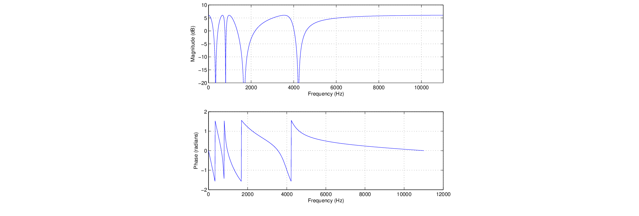
  is to 1.0, the narrower the bandwidth of the notch.
 (180 degrees). This happens close to the center frequencies of each allpass section.
 |
 .
.

| ©2004-2024 McGill University. All Rights Reserved. Maintained by Gary P. Scavone. |
![\begin{figure}\begin{center}
\begin{picture}(3.9,0.8)
\put(0.27,0){\epsfig{fil...
...3.9,0.13){$y[n]$}
\put (1.9,0.75){$g$}
\end{picture} \end{center}
\end{figure}](img20.png)