Next: Room Acoustics Up: Effects Processing Previous: Pitch Shifting
 has a short-term signal level given by
 over the period
  , the dynamic range of the signal is given by
 , and is usually expressed in decibels.
seconds) is given by:
![$\displaystyle \lambda_2(x(t), \tau) = \sqrt{x^2(t) * \left[ \frac{e^{-t/\tau}}{\tau} \cdot u(t)\right]},
$](img45.png)
 denotes convolution and
  is the unit step function. The value of
  is thus formed by squaring the signal , performing a “leaky” integration, and taking the square root of the result.
![$\displaystyle y[n] = b_0 x[n] + a_1 y[n-1] \hspace{0.2in} \Longrightarrow \hspace{0.2in} H(z) = \frac{b_0}{1 - a_1z^{-1}},
$](img49.png)
 for unity gain and
  for filter stability.
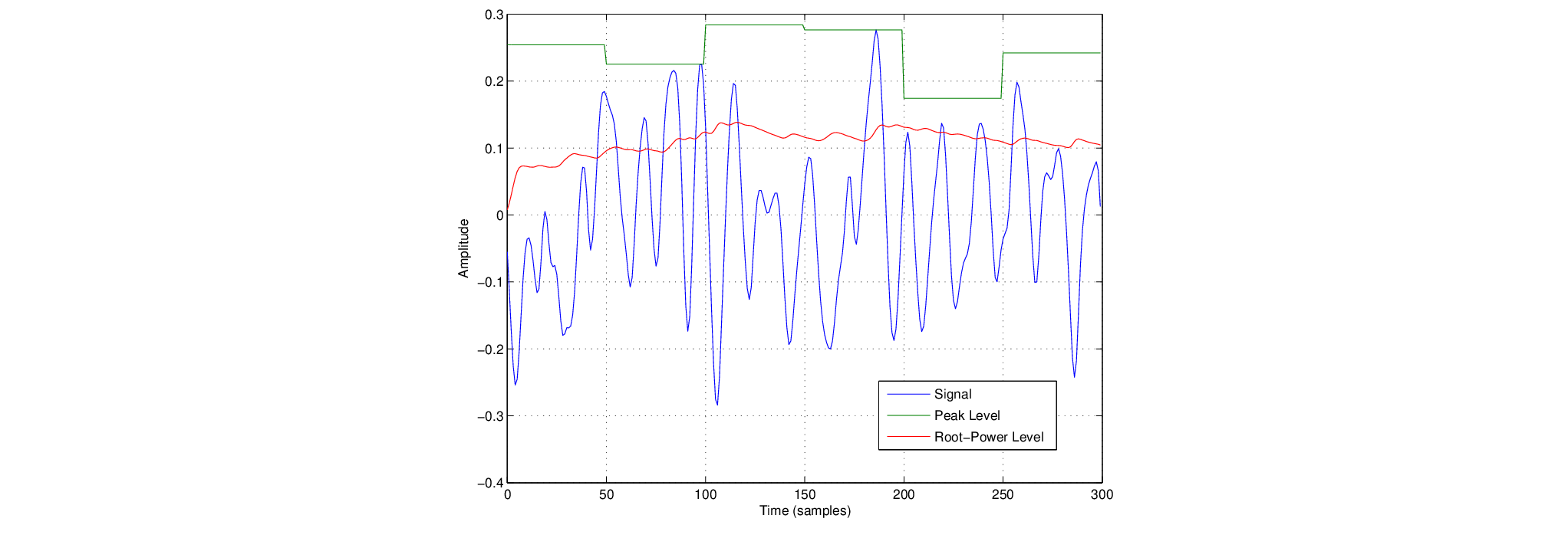
 to a signal, based on an estimate of the signal level.
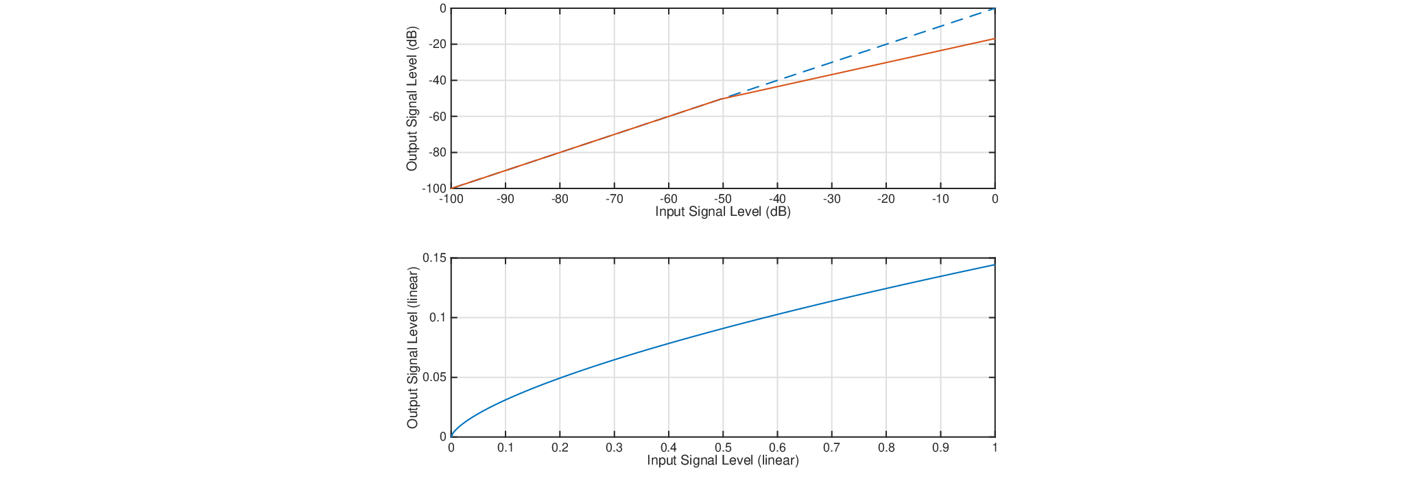
 (near -50 dB in Fig. 6). Beyond , a constant compression ratio is defined by
  such that there is an increase of
  dB in output for every dB increase of the input.
over which the input signal level estimates are calculated has important influence on the response of the compression/expansion system.
value. However, small values of result in more level variance, which is generally undesirable. For this reason, different integration constants are often used for the attack and release portions of a signal.

| ©2004-2024 McGill University. All Rights Reserved. Maintained by Gary P. Scavone. |