Next: Coupling Filter Calibration Up: Coupled Mode Synthesis Previous: A Reformulation
 (4)
(4)
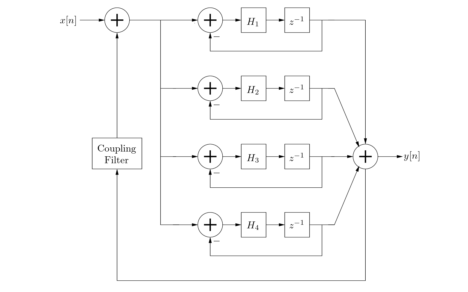
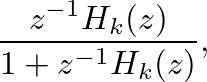
 and unit delay
  in the numerator will have no affect. They will contribute an additional phase component but this will only modify the initial phase of the oscillations.

| ©2004-2024 McGill University. All Rights Reserved. Maintained by Gary P. Scavone. |