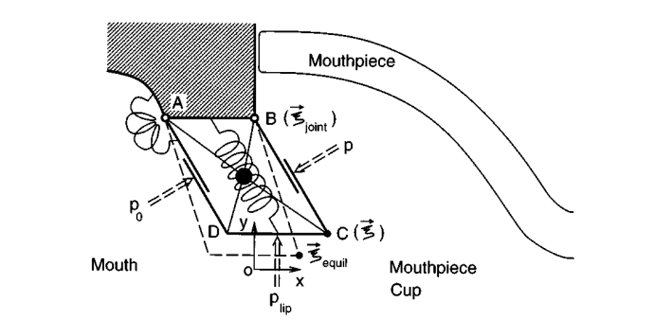
The lip model used in Adachi and Sato (1996) only includes the upper lip, as both lips are assumed to vibrate symmetrically. The lip is represented by the parallelogram ABCD, shown in Figure 1. Oscillation is simultaneously executed through stretching and contraction of the sides AD and BC, caused by Bernoulli force FBernoulli, and through swinging along the hinge AB, caused by the pressure difference F∆p between the player’s blowing pressure p0 and the pressure inside the mouthpiece p. There is assumed to be no compression along the side CD. The location of the lip is tracked through the x- and y-coordinates of point C, ξx and ξy. The restoring forces for both directions of motion are modelled as springs with equal stiffness k.
The equation of lip motion is given by


The area of the mouthpiece entryway, Slip, can be determined geometrically from Figure 1 as

where b is the breadth of the lips, and ξy is the y-coordinate of the lip position, setting the area to zero when the lip is closed. The lip movement generates flow as the lips open and close, and this flow is equivalent to the volume of air swept by the lips per unit time, so the lip volume flow is

Incompressible flow and conservation of mass are assumed, so that the acoustical volume flow rate Uacoust only depends on time t, and not on the place. The lip region is modelled in two regions: the upstream contraction region, inside the player’s mouth, and the downstream expansion region, inside the mouthpiece. The acoustic volume flow is given by solving the sum of equations (7) and (8), which give the volume flow in the upstream and downstream regions, respectively.


The total volume flow rate is given by U = Uacoust + Ulip.
To model the trumpet’s resonance, the reflection function for a specific trumpet is derived from the instrument’s input impedance Zin and the characteristic wave impedance Zc of an infinite cylindrical tube with cross-sectional area Scup using the equation

where .png) is the Fourier transform of r(t). The feedback equation is then given by
is the Fourier transform of r(t). The feedback equation is then given by
