A frequency-domain, transfer-matrix method for modeling piece-wise conical sections, as previously presented for cylindrical sections, is possible. The matrix elements are a bit more complicated, but the approach is well documented and validated and can include accurate characterizations of thermoviscous losses. In this section, however, we focus on the time-domain, traveling-wave approach for modeling combinations of conical sections.
Figure 10:
Junction of two conical tube sections.
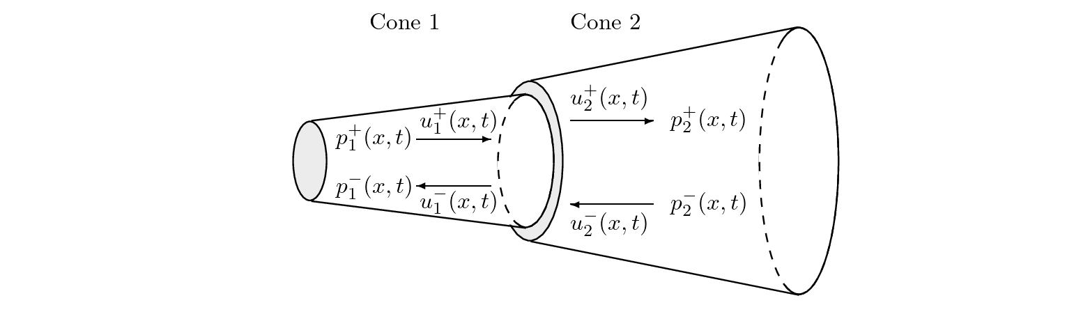 |
- At the boundary of two discontinuous and lossless conical sections, Fig. 10, the abrupt change in diameter and rate of taper will cause scattering of traveling wave components.
- Assuming continuity of pressure and conservation of volume flow at the boundary,
 (29)
(29)
and
 (30)
(30)
where  is the characteristic admittance for section
  at the boundary looking in the positive
  direction.
- The characteristic admittance for spherical waves in a cone is given by
 (31)
(31)
where
 applies to traveling-wave components propagating away from the cone apex in the positive direction and
 to traveling-wave components propagating toward the cone apex in the negative direction.
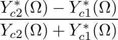
- Solving for
 at the junction,
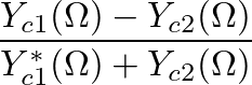
![$\displaystyle P_{1}^{-}(\Omega) = \left[\frac{Y_{c1}(\Omega) - Y_{c2}(\Omega)}{...
...st}(\Omega)}{Y_{c1}^{\ast}(\Omega) + Y_{c2}(\Omega)}\right] P_{2}^{-}(\Omega).
$](img159.png) (32)
(32)
- The frequency-dependent scattering coefficient that relates
to
 is
is
where  is the ratio of wave front surface areas
  at the boundary and
  is given by
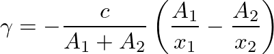 (34)
(34)
(Martínez and Agulló, 1988; Gilbert et al., 1990).
- This reflectance is given a negative superscript to indicate scattering in the negative direction.
- The parameters
 and
and  are measured from the (imaginary) apices of cones and
  , respectively, to the discontinuity.
- Similarly, the expression for
 at the junction is
![$\displaystyle P_{2}^{+}(\Omega) = \left[\frac{Y_{c1}(\Omega) + Y_{c1}^{\ast}(\O...
...st}(\Omega)}{Y_{c2}(\Omega) + Y_{c1}^{\ast}(\Omega)}\right] P_{2}^{-}(\Omega),
$](img171.png) (35)
(35)
and the reflectance that relates
to
 is
is
- This reflectance is given a positive superscript to indicate scattering in the positive direction.
- The scattering equations can then be expressed in terms of
 and
and
 as
as
- It is possible to define transmittances that indicate scattering through the junction as
 and
and
- These expressions are equally valid when either acoustic section is cylindrical, rather than conical. Replacing cone by a cylindrical section,
 and
and  is given by the cylinder's cross-sectional area at the discontinuity.
- Whereas the junction scattering coefficients for cylindrical bore diameter discontinuities were real and constant, these expressions are frequency-dependent and must be transformed to discrete-time filters for time-domain implementation.
- Figure 11(a) illustrates the general scattering junction implementation for diameter and taper discontinuities in conical bores.
Figure 11:
(a) The scattering junction for diameter and taper discontinuities in conical bores; (b) The one-multiply scattering junction for a taper discontinuity only [after (Välimäki, 1995)].
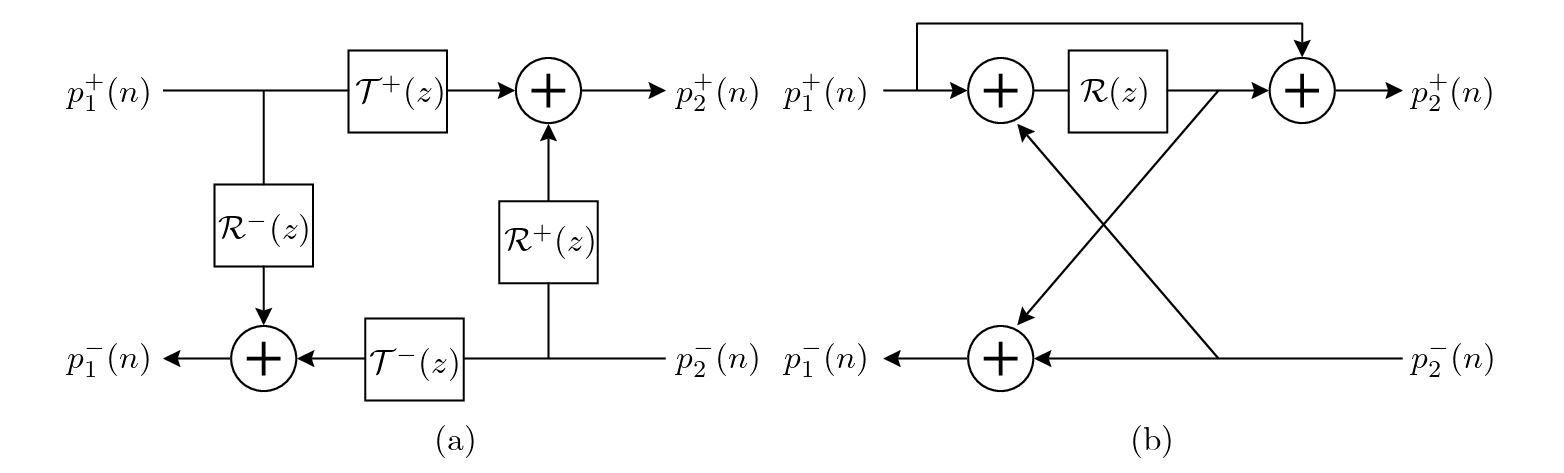 |
- Because
and
are different, the one-multiply form of the scattering junction implementation is not possible.
- However, if the wavefront surface areas are approximated by cross-sectional areas at the discontinuity, which is reasonable only for small changes in taper rate and cross-section, the reflectances
 and
and
 become identical for a discontinuity of taper only. In this case, a one-multiply scattering junction implementation is possible, as shown in Fig. 11(b) (Välimäki, 1995).
- Strictly speaking, however, the propagating wave fronts in cones are spherical and thus
and
will never be identical, even for a simple taper discontinuity.
- Equation (33) can be transformed to the time domain, resulting in the reflection function
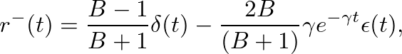 (39)
(39)
where  is the Dirac impulse and
  is the Heaviside unit step function (Martínez and Agulló, 1988).
- An appropriate discrete-time filter is found by making the bilinear transform frequency variable substitution in Eq. (33) with the result
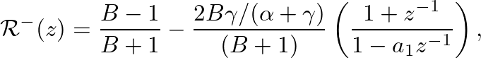 (40)
(40)
where is as given in Eq. (34),  is the bilinear transform constant, and
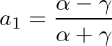 (41)
(41)
is the first-order filter pole location in the  plane.
- Unfortunately,
 is unstable for negative
  which occurs any time cone has a lower rate of taper than cone
- Equivalently,
has no causal inverse Fourier transform for negative

- This corresponds to a growing exponential in the reflection function

- The reflectance is a junction characteristic that is “blind” to the boundary conditions upstream or downstream from it. Physically realistic boundary conditions in such cases, however, will always limit the time duration over which the growing exponential can exist.
- Experimental measurements of reflection functions due to discontinuities have verified this general behavior (Agulló et al., 1995).
- The problem here in terms of digital waveguide modeling, is that the growing exponentials become unstable digital filters in the discrete-time domain.

| ©2004-2024 McGill University. All Rights Reserved.
Maintained by Gary P. Scavone.
|


![$\displaystyle \mathcal{R}^{-}(\Omega) P_{1}^{+}(\Omega) + \left[1 + \mathcal{R}^{+}(\Omega) \right] P_{2}^{-}(\Omega)$](img179.png)

![$\displaystyle \left[1 + \mathcal{R}^{-}(\Omega) \right] P_{1}^{+}(\Omega) + \mathcal{R}^{+}(\Omega) P_{2}^{-}(\Omega).$](img181.png)