Next: Delay-Based Effects Up: Sound and Wave Phenomena Previous: Simulating Sound Wave Propagation
 ), which specifies the ratio of reflected to incident wave energy. Materials that are very reflective will have a value of close to 1, while will be close to zero for materials that are very absorptive. In general, the reflection coefficient will be frequency dependent.
 and
and  account for losses over the respective direct and reflected paths due to the combined effects of air absorption and spherical spreading. If the floor had a reflection coefficient less than one, this could also be included in the factor.
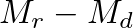 is found as:
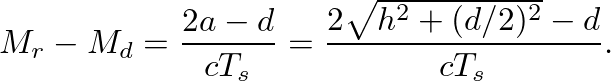
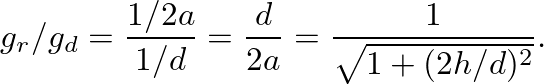
 as:
as:

| ©2004-2024 McGill University. All Rights Reserved. Maintained by Gary P. Scavone. |

![\begin{figure}\begin{center}
\begin{picture}(4,2.5)
\put(0.27,1.5){\epsfig{fil...
...6){$z^{-M_r}$}
\put (3.9,2.24){$y[n]$}
\end{picture} \end{center}
\end{figure}](img27.png)