Next: Householder Feedback Matrices Up: Artificial Reverberation Previous: Feedback Delay Networks (FDN)
![$\displaystyle \mathbf{M} = \left[
\begin{array}{lll}
m_{11} & m_{12} & m_{13} \\
m_{21} & m_{22} & m_{23} \\
m_{31} & m_{32} & m_{33}
\end{array}\right]
$](img43.png)
![$\displaystyle \left[
\begin{array}{l}
x_{1}(n) \\ x_{2}(n) \\ x_{3}(n)
\end{...
...] +
\left[
\begin{array}{l}
b_{1} \\ b_{2} \\ b_{3}
\end{array}\right] u(n)
$](img44.png)
![$\displaystyle v(n) =
\left[
\begin{array}{lll}
c_{1} & c_{2} & c_{3}
\end{a...
...in{array}{l}
x_{1}(n-M_1) \\ x_{2}(n-M_2) \\ x_{3}(n-M_3)
\end{array}\right]
$](img45.png)

![$\displaystyle \mathbf{D}(z) \ensuremath{\stackrel{\Delta}{=}}\left[
\begin{arr...
...{-M_1} & 0 & 0 \\
0 & z^{-M_2} & 0 \\
0 & 0 & z^{-M_3}
\end{array}\right]
$](img47.png)
 is called the state transition matrix.
  is typically a diagonal matrix of lowpass filters, each having gain no greater than 1.
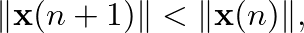
![$\mathbf{x}[n]$](img50.png) decreases over time when the input signal is zero:
decreases over time when the input signal is zero:
 , where
![$\displaystyle \mathbf{x}(n + 1) = \mathbf{A} \left[
\begin{array}{l}
x_{1}(n-M_1) \\ x_{2}(n-M_2) \\ x_{3}(n-M_3)
\end{array}\right].
$](img53.png)
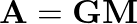
, where  is any orthogonal matrix and is a diagonal matrix having entries less than 1 in magnitude.
 is lossless if and only if its eigenvalues have modulus 1 and its
  eigenvectors are linearly independent.

| ©2004-2024 McGill University. All Rights Reserved. Maintained by Gary P. Scavone. |