Next: Model Generalizations Up: Cylindrical Air Column Modeling Previous: Cylindrical Air Column Modeling
 (34)
(34)
 (35)
(35)
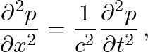
where the spatial sampling distance is given by 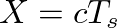 and the time sampling interval is
 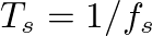 .
.
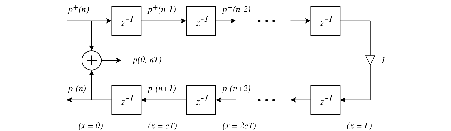 |
 implements the low-frequency, open-end approximation for traveling-wave pressure reflection.
 is given by
where
is given by
where  is the real characteristic wave impedance of the cylindrical pipe, and
  is the load impedance at
 which corresponds to zero pressure at
 The resulting continuous-time reflection function
 is found as the inverse Fourier transform of
 when viscothermal losses are ignored.

| ©2004-2024 McGill University. All Rights Reserved. Maintained by Gary P. Scavone. |

![$\displaystyle \mathcal{R}(\omega) = e^{-2jkL}\left[\frac{Z_{L}(\omega) - Z_{c}}{Z_{L}(\omega) + Z_{c}}\right],
$](img142.png)