Next: A Three-Port Tonehole Model Up: Tonehole Modeling Previous: Tonehole Modeling
 section, as shown in Fig. 1 (Keefe, 1981).
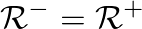
 result from an analysis of anti-symmetric pressure distribution, or a pressure node, at the tonehole junction. In this case, volume flow is symmetric and equal across the junction.
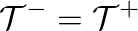
 results from an analysis of symmetric pressure distribution, or a pressure anti-node, at the tonehole, for which pressure is symmetric and equal across the junction.
 Eq. (1) can be reduced to the form
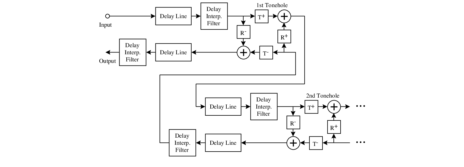
which is the basic tonehole unit cell given by Keefe for transfer-matrix calculations.
Eq. (1) can be reduced to the form
which is the basic tonehole unit cell given by Keefe for transfer-matrix calculations.
 and
and  vary according to whether the tonehole is open (o) or closed (c) as
 is the characteristic impedance of the cylindrical bore, which is equal on both sides of the tonehole.
 |

| ©2004-2024 McGill University. All Rights Reserved. Maintained by Gary P. Scavone. |

![$\displaystyle \left[\begin{array}{c} P_{1} \\ U_{1} \end{array}\right]$](img10.png)

![$\displaystyle \left[\begin{array}{cc} 1 & Z_{a}/2 \\ 0 & 1 \end{array}\right] ...
... 1 \end{array}\right] \left[\begin{array}{c} P_{2} \\ U_{2} \end{array}\right]$](img12.png)
![$\displaystyle \left[\begin{array}{cc} 1 + \frac{Z_{a}}{2 Z_{s}} & Z_{a} \left(1...
...} \end{array}\right] \left[\begin{array}{c} P_{2} \\ U_{2} \end{array}\right].$](img13.png)
![$\displaystyle \left[\begin{array}{c} P_{1} \\ U_{1} \end{array}\right] = \left[...
...1 \end{array}\right] \left[\begin{array}{c} P_{2} \\ U_{2} \end{array}\right],
$](img15.png)


![$\displaystyle \left[\begin{array}{c} P_{1} \\ U_{1} \end{array}\right] = \left[...
...{1}^{-} \\ Z_{c}^{-1} \left( P_{1}^{+} - P_{1}^{-} \right) \end{array}\right],
$](img26.png)
![$\displaystyle \left[\begin{array}{c} P_{1}^{-} \\ P_{2}^{+} \end{array}\right] ...
...rray}\right] \left[\begin{array}{c} P_{1}^{+} \\ P_{2}^{-} \end{array}\right],
$](img28.png)