Next: Register Hole Models Up: Tonehole Modeling Previous: A Two-Port Tonehole Model
 (11)
(11)
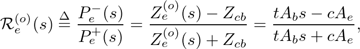
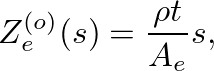
 is the density of air,
  is the cross-sectional area of the end hole,
  is the effective length of the opening (
 ), and
  is the Laplace transform frequency variable.
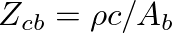 is the characteristic impedance of the tonehole branch waveguide,
  is the cross-sectional area of the branch and
  is the speed of sound.
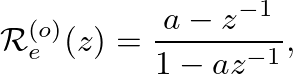
 can be obtained using the conformal bilinear transform from the -plane to the
  -plane (Oppenheim and Schafer, 1989, pp. 415-430), with the result
 (13)
(13)
 (14)
(14)
 is the bilinear transform constant that controls frequency warping.
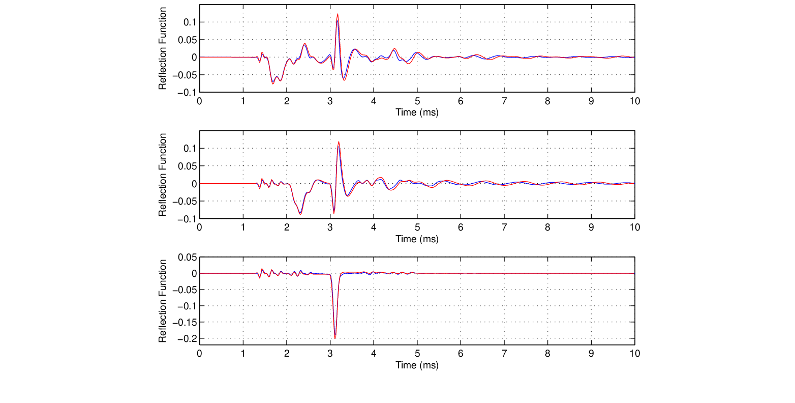
 is a first-order allpass filter, which is consistent with reflection from a “masslike” impedance.
) smoothly to zero.
 the reflectance phase delay is nearly zero for all frequencies, which corresponds well to pressure reflection at a rigid termination.
 |

| ©2004-2024 McGill University. All Rights Reserved. Maintained by Gary P. Scavone. |