Next: The Reed-Spring Solution Up: Reed Valve Modeling Previous: Vibrations of the Reed
 ) and velocity (
 ) at any two points of height
  within a continuous tube of flow, the Bernoulli equation is given by
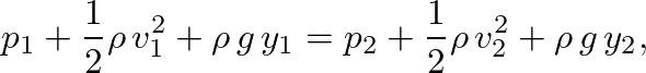 (20)
(20)
 is fluid density and
  is the acceleration of gravity. This expression is based on continuity of volume flow and conservation of energy.
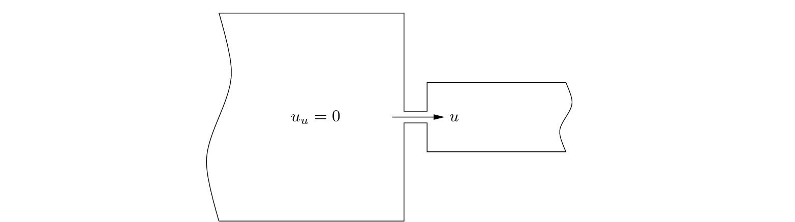
 and essentially zero volume flow
  .
.
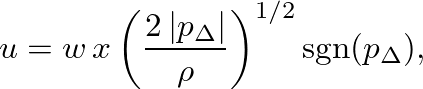
 and
and  are the width and height of the reed channel, respectively, and the sign function is
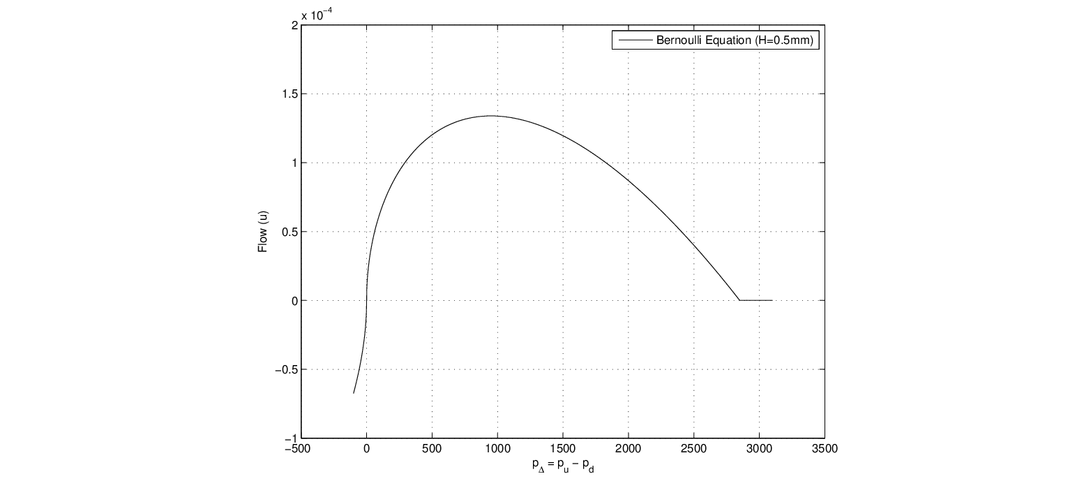
 , the resistance is given by a small positive value. At very high pressure differences, the reed is blown closed against the mouthpiece facing and all flow ceases.

| ©2004-2024 McGill University. All Rights Reserved. Maintained by Gary P. Scavone. |