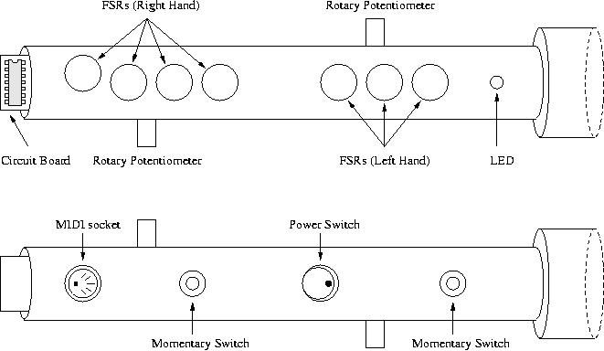

Figure 1. The Pipe from above (top) and below (bottom).


Figure 1. The Pipe from above (top) and below (bottom).
The Pipe was conceived as a standalone, battery powered device which would provide a set of finger ``keys'' in a configuration akin to a musical recorder, as well as contain all necessary circuitry to process the sensor data and output MIDI-formatted control messages. A housing was fabricated from 1.5 inch (3.8 centimeter) inner diameter Acrylonitrile Butadiene Styrene (ABS) piping, cut to a length of approximately 14 inches (35.5 centimeters). A small circuit board was cut so that it could be slid in and out of The Pipe along a set of grooves at its downstream end. This layout is diagrammed in Fig. 2.

Figure 2. The Pipe layout diagram: View from above (top) and below (bottom).
The finger keys or switches on all commercial wind controllers provide only limited, binary state information. When a key is depressed or touched, a new MIDI ``Note On'' message is produced which corresponds to some predefined fingering/note number mapping. A previous controller by this author (The Holey Controller) used FSRs in conjunction with finger keys to enable a 7-bit range of finger position data. The Pipe was designed so that the fingers rest directly on or above FSRs. A set of seven finger depressions were drilled along the length of The Pipe in a traditional two-hand arrangement. Circular force sensing resistors of 3/4 inch diameter were positioned in the depressions and slots were chiseled for the FSR leads to facilitate an internal wiring system. Initially, the FSRs were covered with only a thin layer of tape and direct finger pressure was applied to them. Later, compressible, foam-like pads were added on top of the FSRs to provide some haptic feedback in the fingering mechanism.
Traditional wind instruments are driven by dynamic air flow through an acoustic air column. Most commercial digital wind instrument controllers have made use of similar breath control schemes (Yamaha WX5, Akai EWI). In an electronic wind controller, this air flow is completely unnecessary and even undesirable given potential complications involved with humid air flow through or near electronic components. In addition, the limited capacity of the human lungs requires that outgoing air flow, and the resulting pressure, be periodically stopped. Pressure sensing in The Pipe was therefore based on a static air flow paradigm within an air tight enclosure on the upstream end of the instrument. A removable, contoured mouth cap was designed to be positioned against the performer's face but beyond the mouth and lips to minimize hygienic concerns that might arise when sharing the device. In this scheme, an air-tight seal is formed between the player's face and the cap which allows pressure to be maintained and controlled indefinitely inside the cap while breathing normally through the nose. The mouth cap was fabricated from a short, ABS coupling section.
A variety of additional sensors are included in The Pipe. An earlier controller by this author (The Phoney Controller)) provided tilt sensing in two dimensions using a dual-axis accelerometer. Experience with that device indicated that tilt offers a convenient control parameter that is especially easy to use concurrently with other input sensors. In addition, accelerometers are naturally suited for sensing gestures appropriate when controlling shaker synthesis algorithms. Two rotary potentiometers allow for small or subtle control value variations, as well as a means for setting values which are intended to remain fixed until further modified. These controls were added to address limitations with the use of FSRs, which are difficult to use for precise control and which require continuous action on the part of the player to maintain a non-zero value. Two momentary switches were provided for use as triggers or in conjunction with other sensors to create more complex control schemes.
The electronic components were mounted on a circuit board which was cut so that it could be slid into the downstream end of the ABS housing. The FSRs (Interlink Electronics), switches, potentiometers, MIDI socket, and LED were mounted on the ABS housing (see Fig. 2) and connected to the circuit board via ribbon cables. The BSIIsx is powered by a 9-volt battery, which is housed inside The Pipe just below the detachable mouthpiece.

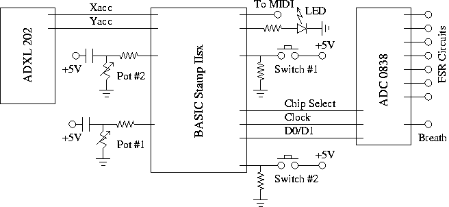
Figure 3. The Pipe circuit schematic.
The circuit board schematic is shown in Fig. 3. The dual-axis accelerometer, an Analog Devices ADXL202, provides digital output and interfaces to the BSIIsx via two of its sixteen input/output pins. The potentiometers and momentary switches are connected via one input pin each. The MIDI interface jack uses one output pin. The seven FSRs and the air pressure sensor are read through an 8-channel, 8-bit serial I/O multiplexing analog-to-digital converter (National Semiconductor ADC0838), which connects to the microprocessor using three pins. Currently, a Motorola MPXV5010 air pressure sensor is being used with a range of 0 to 1.45 PSI. In the future, a more sensitive device may be substituted. Finally, an LED was included via another pin as a visual feedback mechanism to distinguish program features. In its current form, five input/output pins remain for future modifications or upgrades.
A single MIDI cable is necessary to connect with an external synthesizer or computer. A removable, four-pin connector provides a serial interface to a computer for microprocessor programming. The BASIC Stamp makes use of a simplified and customized form of the BASIC programming language called PBASIC. Up to eight programs can be stored in 2 Kbytes of memory each. The scaling of sensor data for 7-bit MIDI message output is left completely to the programmer.