Next: Input Impedance Calculations Up: Conical Air Column Modeling Previous: Modeling a Single Conic Section
 and pressure traveling-wave components reflect from the cone apex with a
  phase shift (or an inversion).
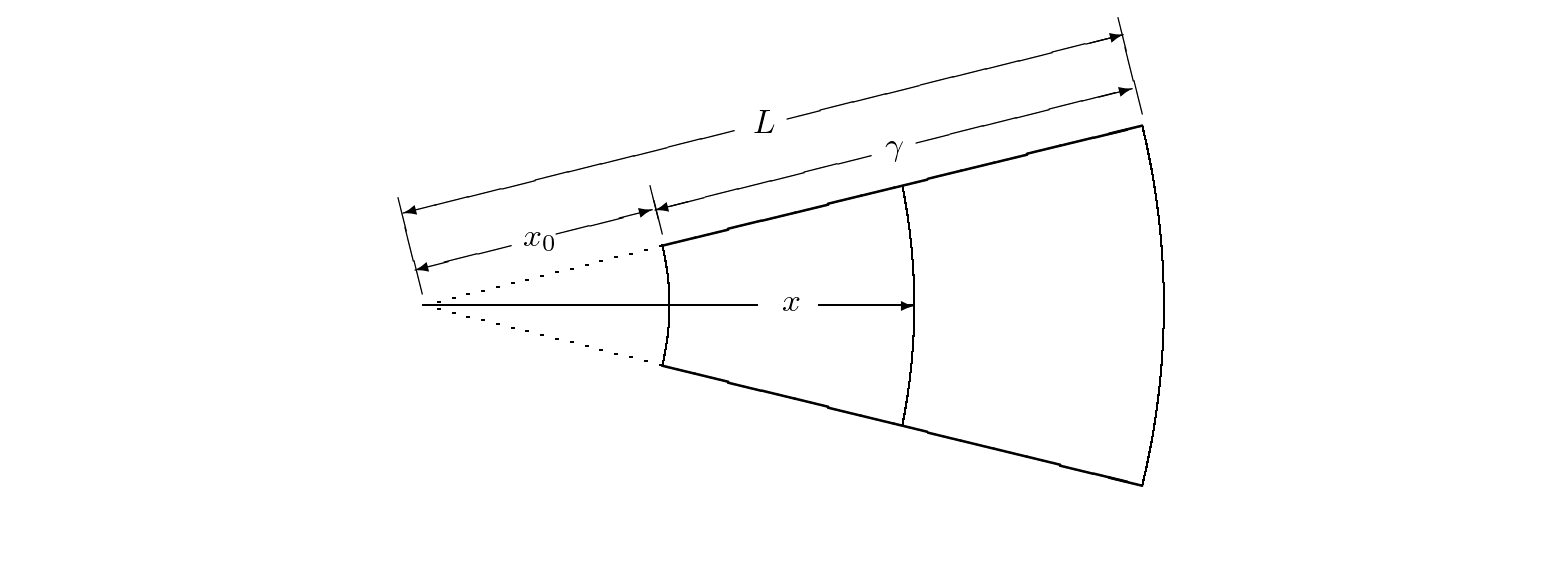
 from its apex.
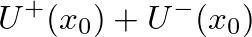
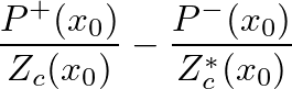
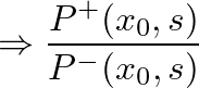
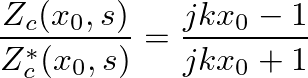
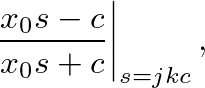
is found from the boundary condition  such that
 is the Laplace transform variable and
  is the speed of sound in air.
 the reflectance approaches negative one as observed above.
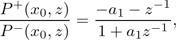
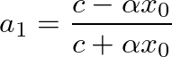
 is the bilinear transform constant that controls frequency warping.
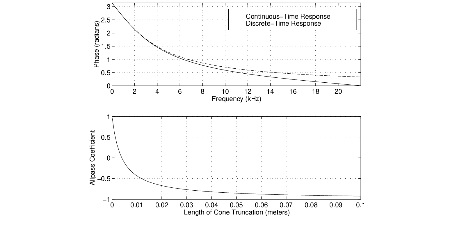
 frequency-dependent phase delay experienced by pressure traveling-wave components reflecting from a rigid termination in a conical waveguide.
the filter becomes unstable because
 and the allpass pole falls on the unit circle. Thus, the truncation filter cannot be used to simulate a complete cone, but in this case the reflectance is simply negative one anyway.
 |

| ©2004-2022 McGill University. All Rights Reserved. Maintained by Gary P. Scavone. |