Next: Cylindrical Sections: Time-Domain Approach Up: Cylindrical Air Column Modeling Previous: Impulse Response
 in a cylindrical pipe of finite length is given by
![$\displaystyle P(x,t) = \left[C^{+}e^{-jkx} + C^{-}e^{jkx}\right] e^{j\omega t},
$](img93.png) (37)
(37)
 and
and  are complex traveling-wave amplitudes,
 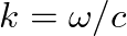 is the wave number,
  is radian frequency, and
  is the speed of sound in air.
![$\displaystyle U(x,t) = \frac{1}{Z_{c}}\left[C^{+}e^{-jkx} - C^{-}e^{jkx}\right] e^{j\omega t},
$](img159.png) (38)
(38)
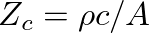 is the real-valued wave impedance of the pipe and
  is its cross-sectional area.
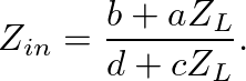
 to
to  and is terminated at by the load impedance
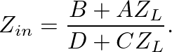
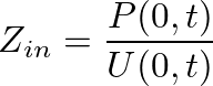
  , it is possible to derive (from the equations above) an expression for the impedance at
  or the input impedance of the cylindrical pipe, given by
 as
as
![$\displaystyle \left[\begin{array}{c} P_{0} \\ U_{0} \end{array}\right] = \left[...
...d \end{array}\right] \left[\begin{array}{c} P_{L} \\ U_{L} \end{array}\right],
$](img161.png) (41)
(41)
 (42)
(42)
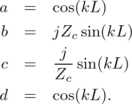
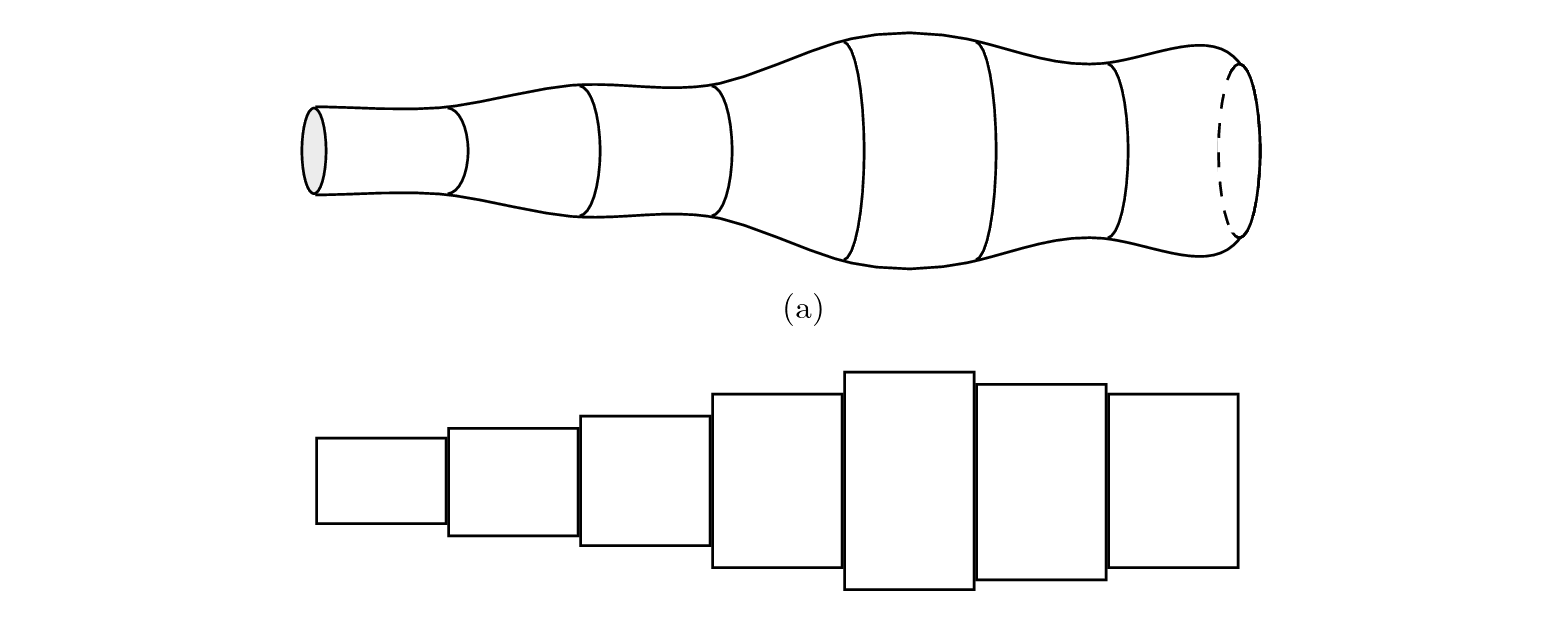
 cylindrical sections, the input variables for each section become the output variables for the previous section. The transfer matrices can then be cascaded as
![$\displaystyle \left[\begin{array}{c} P_{0} \\ U_{0} \end{array}\right]$](img164.png) |
 |
![$\displaystyle \left[\begin{array}{cc} a_{1} & b_{1} \\ c_{1} & d_{1} \end{arra...
...n} \end{array}\right] \left[\begin{array}{c} P_{L} \\ U_{L} \end{array}\right]$](img165.png) |
|
|
![$\displaystyle \left[\begin{array}{cc} A & B \\ C & D \end{array}\right] \left[\begin{array}{c} P_{L} \\ U_{L} \end{array}\right]$](img166.png) |
(43) |
![$\displaystyle \left[\begin{array}{cc} A & B \\ C & D \end{array}\right] = \prod...
...{n} \left[\begin{array}{cc} a_{i} & b_{i} \\ c_{i} & d_{i} \end{array}\right],
$](img167.png) (44)
(44)
 (45)
(45)
 .
.

| ©2004-2024 McGill University. All Rights Reserved. Maintained by Gary P. Scavone. |
![$\displaystyle Z_{c}\left[\frac{C^{+} + C^{-}}{C^{+} - C^{-}}\right]$](img117.png)
![$\displaystyle Z_{c}\left[\frac{Z_{L} \cos (kL) + j Z_{c} \sin(kL)}{jZ_{L} \sin(kL) + Z_{c} \cos(kL)}\right].$](img118.png)