Next: The “Cyclone” Up: Synthesizing Conical Instrument Sounds Previous: Properties of Conic Frusta
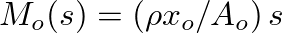 , where
  is the mass density of air,
  is the area of the spherical wavefront at the waveguide input, and
  is Laplace transform frequency variable.
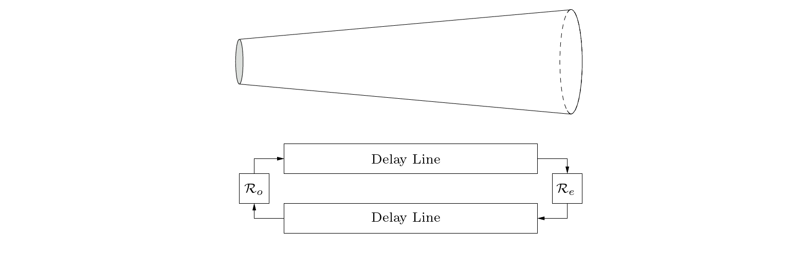
 and an input load impedance. If the input is rigidly terminated, the input load is infinite and the pressure-wave reflectance is given by:
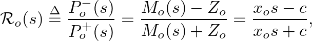
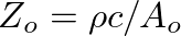 is a real, locally defined characteristic impedance parameter.
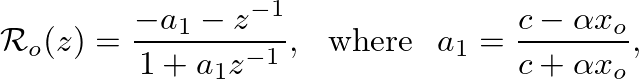
 is the bilinear transform constant that controls frequency warping.
 , tends to be less significant than that at the input, particularly in the presence of an open-end load impedance. In general, a single output reflectance filter can be designed based on the parallel combination of and an appropriate open-end impedance characterization.

| ©2004-2022 McGill University. All Rights Reserved. Maintained by Gary P. Scavone. |