The “cyclone” conical bore model is based on a compound cylindrical-conical segment air column model as illustrated at the top of Fig. 19.
Figure 19:
“Cyclone” physical structure (top) and digital waveguide block diagram (bottom).
The input cylindrical section roughly models the instrument mouthpiece cavity and its use avoids the complications previously discussed with respect to the non-linear driver.
In addition, the cylindrical section can be designed to have an equivalent volume equal to the missing conic section volume. Assuming no diameter discontinuity at the cylinder-cone junction, this constraint is met using a cylindrical section length equal to .
It should be noted that Benade distinguishes between a cavity's physical and equivalent volumes under playing conditions, which are typically not the same. For the simplified reed function used in this implementation, however, it is reasonable to ignore this difference.
The cylinder-cone junction filter is derived assuming continuity of pressure and conservation of volume velocity and then discretized using the bilinear transform as:
where 
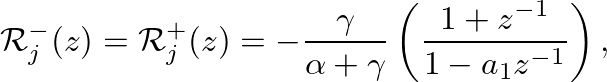
is the bilinear transform constant,
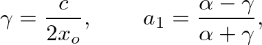
is the speed of wave propagation in the structure, and is the length of the truncated conic section.
This expression could just as well have been derived from the parallel combination of the input inertance and the wave impedance of the input cylindrical section.
The junction transmittance magnitude response (
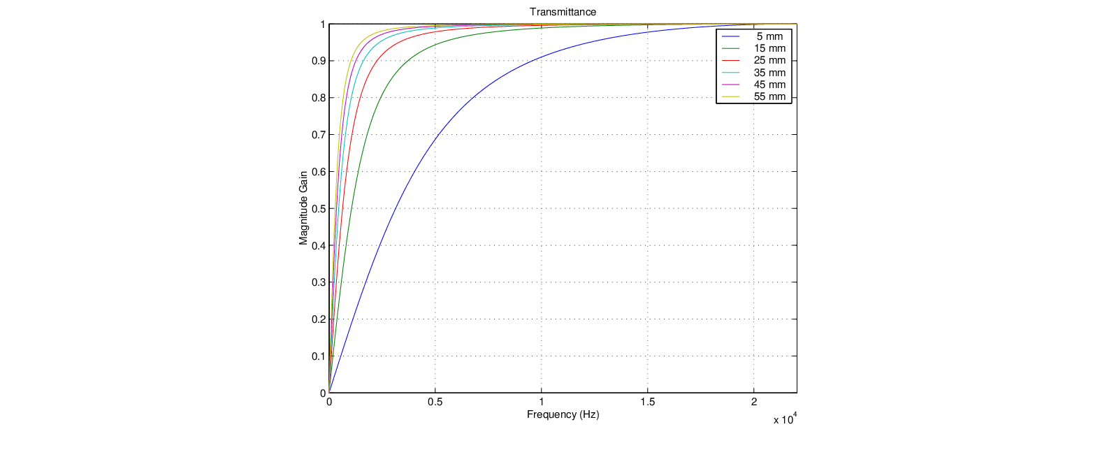
) is shown in Fig. 20 for various values of .
Figure 20:
The cylinder-cone junction transmittance for various values of truncation .
The “high-pass” filter characteristic associated with the conical waveguide input inertance term can vary significantly depending on the frustum dimensions.
Shorter values of correspond to steeper flare rates, which produce greater wave discontinuity at the junction and greater low-frequency attenuation.
While this might appear to imply a preference for less steeply flared conic sections, it should be remembered that larger values of 
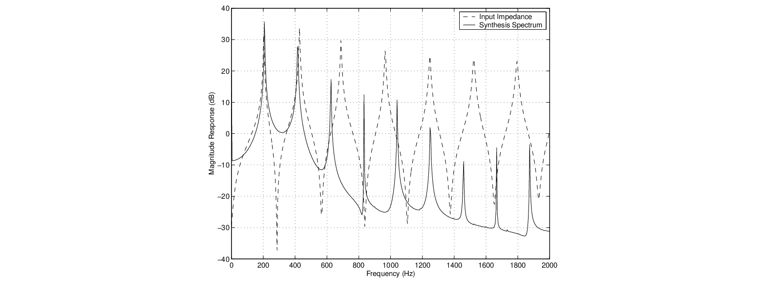
correspond to larger values of in Fig. 15 and thus greater mode inharmonicity. The result is a design conflict between junction discontinuity, which destabilizes the lower air column modes, and mode harmonicity.
The cylinder-cone junction can be implemented using a single first-order digital filter, as discussed by Välimäki and Karjalainen (1994); Smith (1991) and others. A block diagram of the resulting digital waveguide model is shown in Fig. 19.
Figure 21 displays the input impedance and sound spectrum produced by an example “cyclone” waveguide model.
Figure 21:
Example “cyclone” model input impedance and synthesized sound spectrum.
Despite significant inharmonicity of the input impedance peaks, the resulting synthesis spectrum is harmonic and exhibits contributions from “misaligned” peaks as a result of the non-linear regenerative process.
The sounds produced by the “cyclone” model have a distinctive saxophone quality, though the instabilities associated with truncated conic frusta as outlined in earlier sections are present and the functional parameter space can be difficult to assess.